SH2011xxxxLx-xxx Overview
| Part | SH2011xxxxLx-xxx |
|---|---|
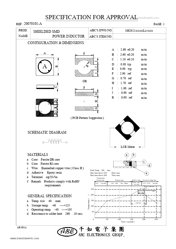
| Description | SHIELDED SMD SHIELDED SMD |
| Manufacturer | ABC Taiwan Electronics |
| Size | 478.25 KB |
| Part Number | Manufacturer | Description |
|---|---|---|
| SMF54CA-MS | Formosa MS | SMD Transient Voltage Suppressor |
| BTP-99XXCT-XX-X | DB Lectro | ProLite 1W SMD Star |
| O3HS | Fox Electronics | HCMOS 3.2 x 2.5mm SMD Oscillator |