Datasheet Details
| Part number | CS212 |
|---|---|
| Manufacturer | Cherry Semiconductor Corporation |
| File Size | 158.19 KB |
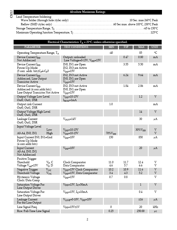
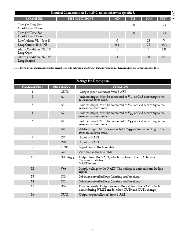
| Description | Security Detector Serial-Addressable Receiver/Transmitter |
| Datasheet |
 CS212 Datasheet CS212 Datasheet
|
|
|
The S-ART is a 16 pin circuit designed for data transmission on a two-lead cable.
The circuit is specially developed for alarm systems where it is desired to identify each detector individually.
There can be up to 30 S-ART circuits/detectors on the same 2-lead cable.

| Part number | CS212 |
|---|---|
| Manufacturer | Cherry Semiconductor Corporation |
| File Size | 158.19 KB |
| Description | Security Detector Serial-Addressable Receiver/Transmitter |
| Datasheet |
CS212 Datasheet
|
|
|
|