IRF4000
Features l l l l l l
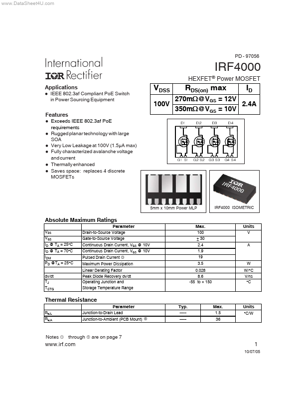
270m:@VGS = 12V 2.4A 350m:@VGS = 10V
' ' ' '
RDS(on) max
Exceeds IEEE 802.3af Po E requirements Rugged planar technology with large SOA Very Low Leakage at 100V (1.5µA max) Fully characterized avalanche voltage and current Thermally enhanced Saves space: replaces 4 discrete MOSFETs
- 6
- 6
- 6
- 6
5mm x 10mm Power MLP
IRF4000 ISOMETRIC
Absolute Maximum Ratings
Parameter
VDS VGS ID @ TA = 25°C ID @ TA = 70°C IDM PD @TA = 25°C dv/dt TJ TSTG Drain-to-Source Voltage Gate-to-Source Voltage Continuous Drain Current, VGS @ 10V Continuous Drain Current, VGS @ 10V Pulsed Drain Current
Max.
100 ± 30 2.4 1.9 19 3.5 0.028 8.6 -55 to + 150
Units
V A c
Maximum Power Dissipation Linear Derating Factor Peak Diode Recovery dv/dt Operating Junction and Storage Temperature Range
W W/°C V/ns °C
Thermal Resistance
Parameter
RθJL RθJA Junction-to-Drain Lead Junction-to-Ambient (PCB Mount)
Typ.
Max.
1.5 36
Units
°C/W f
- -
- -
- -
Notes through
are on...