Datasheet Details
| Part number | MR-J3 |
|---|---|
| Manufacturer | Mitsubishi |
| File Size | 934.12 KB |
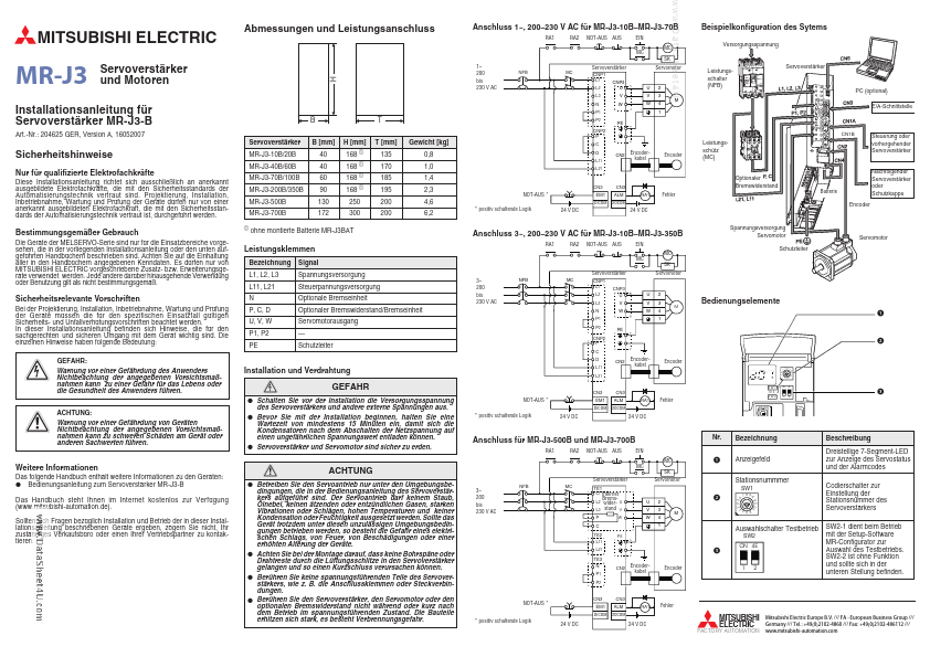
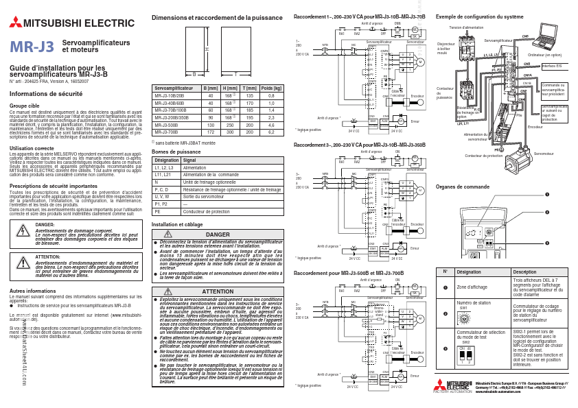
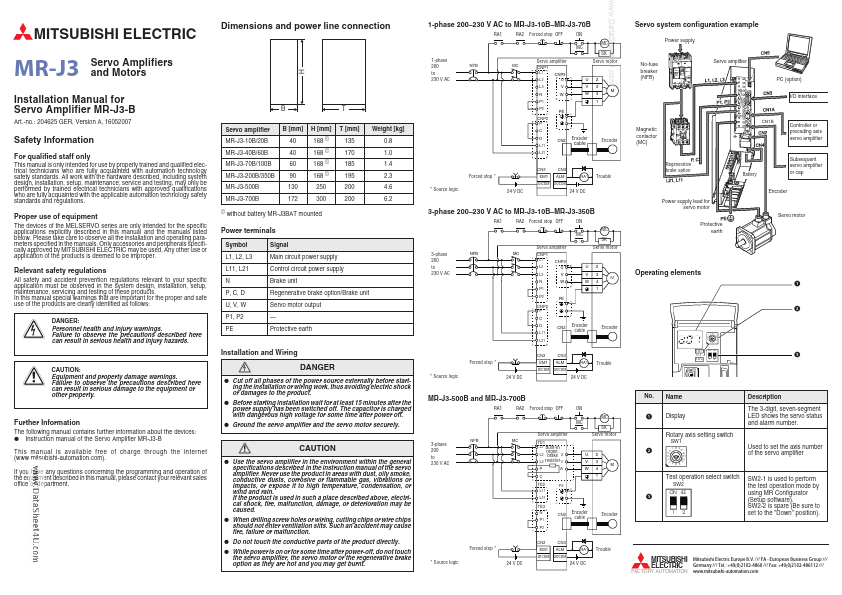
| Description | Servo Amplifiers and Motors |
| Datasheet |
 MR-J3_Mitsubishi.pdf MR-J3_Mitsubishi.pdf
|
|
|
The MR-J3 by Mitsubishi is a Servo Amplifiers and Motors. Below is the official datasheet preview.
| Part number | MR-J3 |
|---|---|
| Manufacturer | Mitsubishi |
| File Size | 934.12 KB |
| Description | Servo Amplifiers and Motors |
| Datasheet |
MR-J3_Mitsubishi.pdf
|
|
|
|
The 3-digit, seven-segment LED shows the servo status and alarm number. 230 V AC für MR-J3-10B MR-J3-70B RA1 RA2 NOT-AUS AUS EIN MC MC SK www.DataSheet4U.com Beispielkonfiguration des Sytems Verso
📁 MR-J3 Similar Datasheet