Datasheet Details
| Part number | MC145705 |
|---|---|
| Manufacturer | Motorola |
| File Size | 229.36 KB |
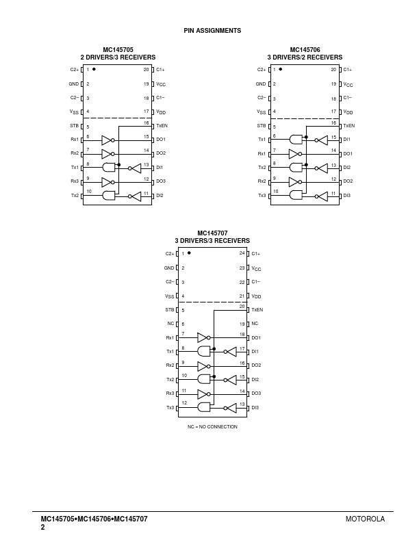
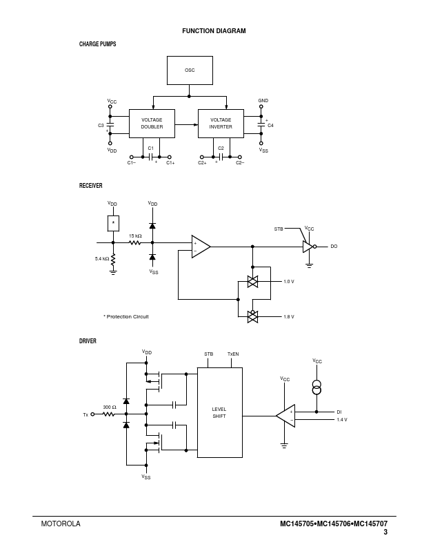
| Description | (MC145706 / MC145707) 5 Volt Only Driver/Receiver with an Integrated Standby Mode |
| Datasheet |
 MC145705 Datasheet MC145705 Datasheet
|
|
|
VCC Digital Power Supply This digital supply pin is connected to the logic power supply.
This pin should have a 0.33 µF capacitor to ground.
232 D connector (Pin 7) as well as to the logic power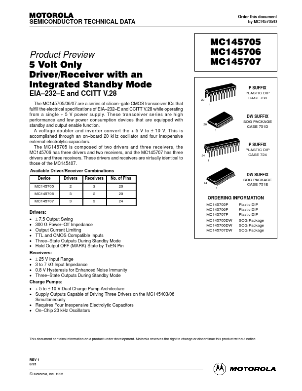
| Part number | MC145705 |
|---|---|
| Manufacturer | Motorola |
| File Size | 229.36 KB |
| Description | (MC145706 / MC145707) 5 Volt Only Driver/Receiver with an Integrated Standby Mode |
| Datasheet |
MC145705 Datasheet
|
|
|
|