Datasheet Details
| Part number | NCP1406 |
|---|---|
| Manufacturer | ON Semiconductor ↗ |
| File Size | 223.65 KB |
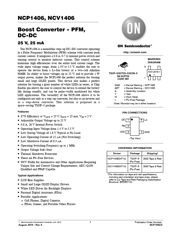
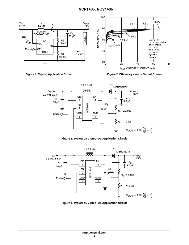
| Description | PFM Step Up DC-DC Converter |
| Datasheet |
 NCP1406_ONSemiconductor.pdf NCP1406_ONSemiconductor.pdf
|
| Part number | NCP1406 |
|---|---|
| Manufacturer | ON Semiconductor ↗ |
| File Size | 223.65 KB |
| Description | PFM Step Up DC-DC Converter |
| Datasheet |
NCP1406_ONSemiconductor.pdf
|
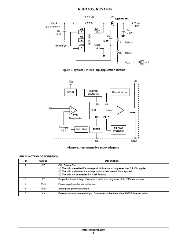
Pin Symbol Description 1 CE Chip Enable Pin (1) The chip is enabled if a voltage which is equal to or greater than 0.9 V is applied.(2) The chip is disabled if a voltage which is less than 0.3 V is applied.(3) The chip will be enabled if it is left floating.2 FB Output feedback voltage.Connected to the inverting input of the PFM comparator.3 VDD Power supply pin for internal circuit 4 GND Analog and power ground pin 5 LX External inductor connection pin.Connected to the drain of
📁 NCP1406 Similar Datasheet