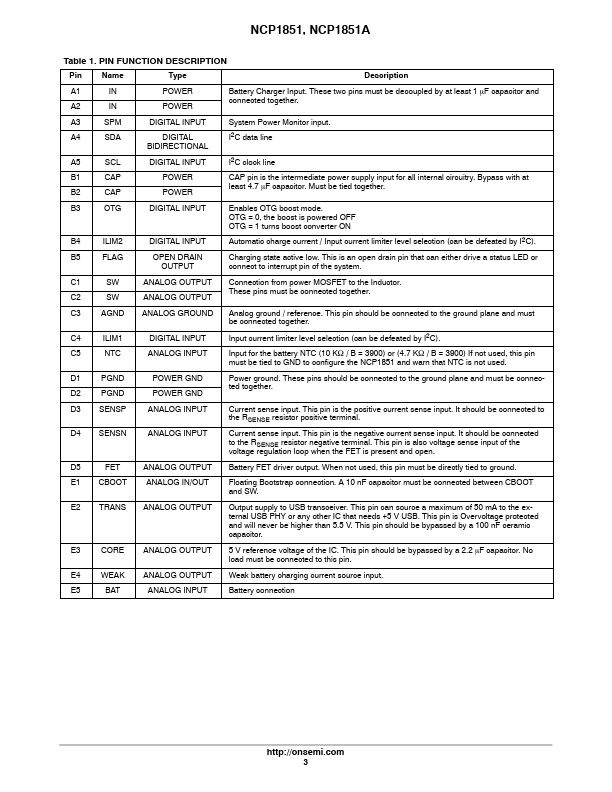
Description
Pin Name
Type
Description
A1 IN A2 IN
POWER POWER
Battery Charger Input.These two pins must be decoupled by at least 1 mF capacitor and connected together.A3 SPM A4 SDA
DIGITAL INPUT DIGITAL
BIDIRECTIONAL
System Power Monitor input.I2C data line
A5 SCL
DIGITAL INPUT
I2C clock line
B1 CAP B2 CAP
POWER POWER
CAP pin is the intermediate power supply input for all internal circuitry.Bypass with at least 4.7 mF capacitor.Must be tied together.B3 OTG
DIGITAL INPUT
Enables OTG b
Features
- under software supervision. An optional battery FET can be placed between the system and the battery in order to isolate and supply the system. The NCP1851 junction temperature and battery temperature are monitored during charge cycle, and both current and voltage can be modified accordingly through I2C setting. The charger activity and status are reported through a dedicated pin to the system. The input pin is protected against overvoltages. The NCP1851 also provides USB OTG support by boosting.
 NCP1851-ONSemiconductor.pdf