Description
PIN NUMBER
1 2 3
4 5
6
7
8
PIN NAME INC U/D
VH/RH
VSS VW/RW RL/VL
CS
VCC
DESCRIPTION
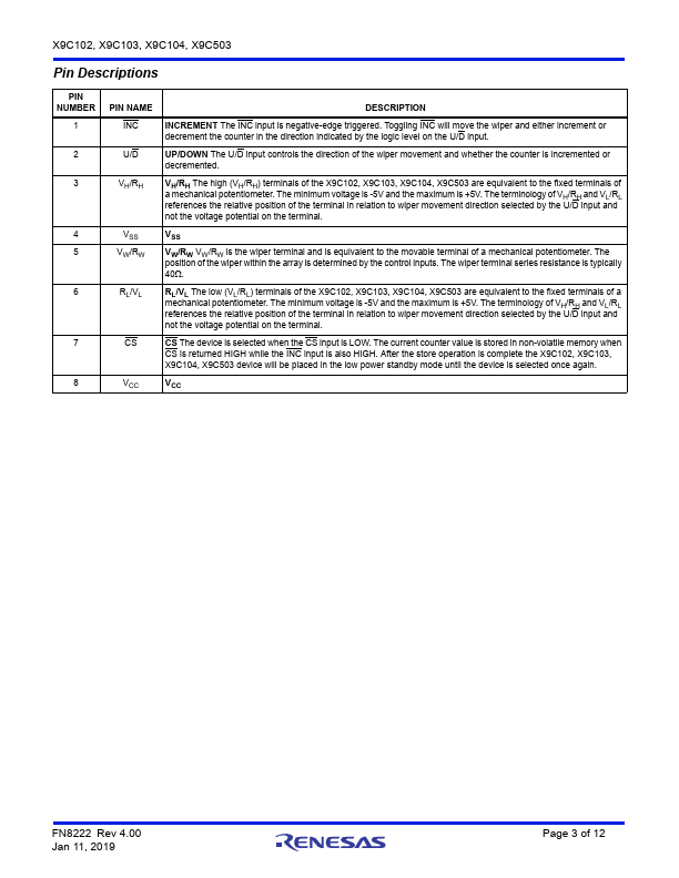
INCREMENT The INC input is negative-edge triggered.Toggling INC will move the wiper and either increment or decrement the counter in the direction indicated by the logic level on the U/D input.UP/DOWN The U/D input controls the direction of the wiper movement and whether the counter is incremented or decremented.VH/RH The high (VH/RH) terminals of the X9C102, X9C103, X9C104, X9C503 are equivalent to the f
Features
- Solid-State Potentiometer.
- Three-Wire Serial Interface.
- 100 Wiper Tap Points - Wiper Position Stored in Non-volatile Memory and Recalled on Power-up.
- 99 Resistive Elements - Temperature Compensated - End-to-End Resistance, ±20% - Terminal Voltages, ±5V.
- Low Power CMOS - VCC = 5V - Active Current, 3mA max. - Standby Current, 750µA max.
- High Reliability - Endurance, 100,000 Data Changes per Bit - Register Data Retention, 100 years.
- X.
 X9C102-Renesas.pdf