Description
Pin name VSS1 VDD1 VDD2 VDD3 VP PORT0 P00 to P07 I/O
Power supply (-)
8 bit input / output port
Data direction programmable in nibble units
Use of pull-up resistors for P1 to P3 and P4 to P7 can be specified in three bit unit and nibble unit respectively.
Input for HOLD release
Input for port 0 interrupt
Other function A/D conversion input port: AN0 to AN7 PORT1 P10 to P17 I/O
8-bit input / output port
Data
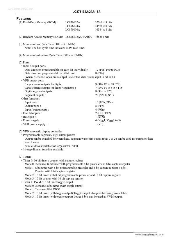
Features
- (1) Read-Only Memory (ROM): LC876132A LC876124A LC876116A 32768 × 8 bits 24576 × 8 bits 16384 × 8 bits 768 × 9 bits
(2) Random Access Memory (RAM): LC876132A/24A/16A (3) Minimum Bus Cycle Time: 100 ns (10MHz) Note: The bus cycle time indicates ROM read time. (4) Minimum Instruction Cycle Time: 300 ns (10MHz)
(5) Ports.
- Input / output ports Data direction programmable for each bit individually : 12 (P1n, P70 to P73) Data direction programmable in nibble unit : 8 (P0n) (When N-channel o.
 LC876116A_SanyoElectric.pdf