Description
Pin description
Pin No.Pin name
1
PWM_CLK
2
VDDIO
3
NCS
4
SDI
5
ISEL2
6
SDO
7
AGND
8
SCLK
9
OSEL1
10
OSEL2
11
PWM1
12
PWM2
13
PWM3
14
PWM4
15
CM1
16
CM2
17
DIAG1
18
DIAG2
19
PGND1
20
PGND1
21
OUT1
22
OUT1
23
OUT2
24
OUT2
25
VBAT
26
VBAT
27
OUT3
28
OUT3
29
OUT4
30
OUT4
TB9053FTG,TB9054FTG
Table 6.1. Pin description
Input/ output
IN Power supply
IN IN IN OUT GND IN IN IN
IN
Pin description
Corner pin (E-PAD) External MCU inputs PWM
Features
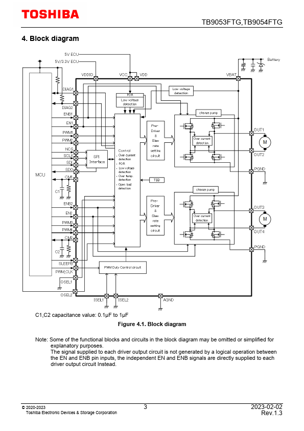
- Motor driver block: Dual-channel, H-bridge driver (Ron(Nch+Nch)) < 350 mΩ (Max @ Tj = 150°C, VBAT = 8 V) Dual-Channel Mode and Combined-Channel Mode selectable, connecting two outputs externally allows this IC to function as a single-channel H-bridge circuit and the device is also used as a 4-channel Half Bridge driver.
- Detection features: Over-current detection, over-temperature detection, VBAT under-voltage detection, and VCC under-voltage detection.
- Initial diagnosis: Power s.
 TB9053FTG-Toshiba.pdf