Datasheet Details
| Part number | WT6003 |
|---|---|
| Manufacturer | W2 Technology |
| File Size | 102.79 KB |
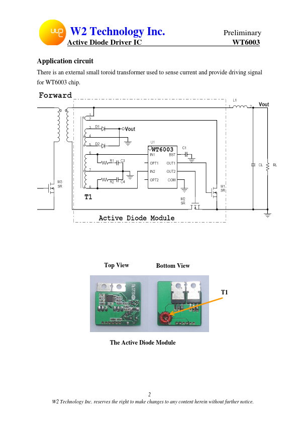
| Description | Active Diode Driver IC |
| Datasheet |
 WT6003 Datasheet WT6003 Datasheet
|
|
|
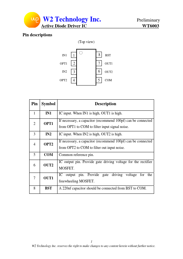
1 IN1 IC input.
When IN1 is high, OUT1 is high.
2 OPT1 from OPT1 to COM to filter input signal noise.
| Part number | WT6003 |
|---|---|
| Manufacturer | W2 Technology |
| File Size | 102.79 KB |
| Description | Active Diode Driver IC |
| Datasheet |
WT6003 Datasheet
|
|
|
|