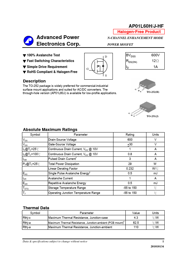
DESCRIPTION
G D S TO-252(H) G D S TO-251(J) ABSOLUTE MAXIMUM RATINGS
Symbol VDS VGS ID@TC=25℃ ID@TC=100℃ IDM PD@TC=25℃ EAS IAR EAR TSTG TJ Parameter Drain-Source Voltage Gate-Source Voltage Continuous Drain Current, VGS @ 10V Continuous Drain Current, VGS @ 10V Pulsed Drain Current 1 Rating 600 +30 1 0.8 3 29 0.232 0.5 1 0.5 -55 to 150 -55 to 150 Units V V A A A W W/ ℃ mJ A mJ ℃ ℃ Total Power Dissipation Linear Derating Factor Single Pulse Avalanche Energy2 Avalanche Current Repetitive Avalanche Energy Storage Temperature Range Operating Junction Temperature Range Thermal Data Symbol Rthj-c Rthj-a Rthj-a Parameter Maximum Thermal Resistance, Junction-case Maximum Thermal Resistance, Junction-ambient (PCB mount) 4 Value 4.3 62.5 110 Units ℃/W ℃/W ℃/W Maximum Thermal Resistance, Junction-ambient Data & specifications subject to change without notice 1 201010134 AP01L60H/J-HF ELECTRICAL CHARACTERISTICS
@Tj=25 C(unless otherwise specified) Symbol BVDSS ∆BVDSS/∆Tj RDS(ON) VGS(th) gfs IDSS IGSS Qg Qgs Qgd td(on) tr td(off) tf Ciss Coss Crss Parameter Drain-Source Breakdown Voltage 3 o Test Conditions VGS=0V, ID=1mA Min. Advanced Power Electronics