ATC AT03115AT
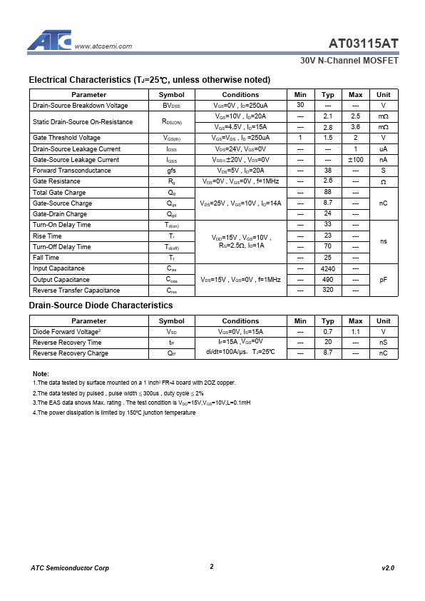
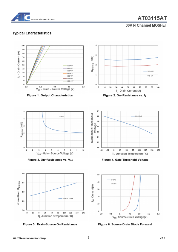
The data tested by surface mounted on a 1 inch2 FR-4 board with 2OZ copper. The test condition is VDD=15V,VGS=10V,L=0.1mH 4.The power dissipation is limited by 150℃ junction temperature ATC Semiconductor Corp 2 v2.0 Typical Characteristics AT03115AT 30V N-Channel MOSFET Figure 1.| Part No. | AT03115AT |
|---|---|
| Datasheet | AT03115AT Download |
| Manufacturer |  ATC |
| Description | 30V N-Channel MOSFET |
| Buy | Stock & Price |
FEATURES
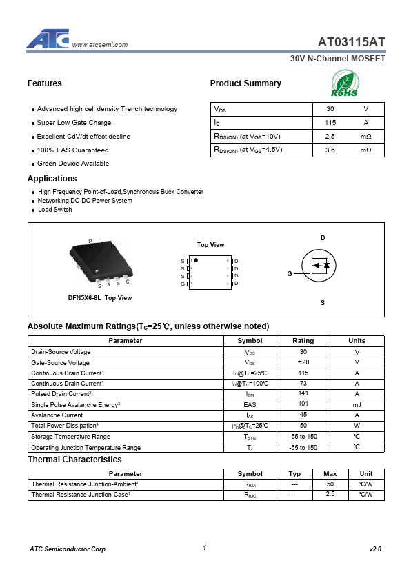
Product Summary● Advanced high cell density Trench technology
● Super Low Gate Charge
● Excellent CdV/dt effect decline
● 100% EAS Guaranteed
● Green Device Available
APPLICATIONS
● High Frequency Point-of-Load,Synchronous Buck Converter● Networking DC-DC Power System
● Load Switch VDS ID RDS(ON) (at VGS=10V) RDS(ON) (at VGS=4.5V) 30 V 115 A 2.5 mΩ 3.6 mΩ DFN5X6-8L Top View Top View S1 S2 S3 G4 8D 7D 6D 5D D G S
ABSOLUTE MAXIMUM RATINGS
(TC=25℃, unless otherwise noted) Parameter Drain-Source Voltage Gate-Source Voltage Continuous Drain Current1 Continuous Drain Current1 Pulsed Drain Current2 Single Pulse Avalanche Energy3 Avalanche Current Total Power Dissipation4 Storage Temperature Range Operating Junction Temperature Range Thermal Characteristics Symbol VDS VGS ID@TC=25℃ ID@TC=100℃ IDM EAS IAS PD@TC=25℃ TSTG TJ Parameter Thermal Resistance Junction-Ambient1 Thermal Resistance Junction-Case1 Symbol RθJA RθJC Rating 30 ±20 115 73 141 101 45 50 -55 to 150 -55 to 150 Units V V...