U2043B
U2043B is Flasher manufactured by Atmel.
Features
Temperature and Voltage pensated Frequency Warning Indication of Lamp Failure by Means of Frequency Doubling Minimum Lamp Load for Flasher Operation ≥ 10W Relay Output with High Current Carrying Capacity and Low Saturation Voltage
- Low Susceptibility to EMI
- -
- -
..
1. Description
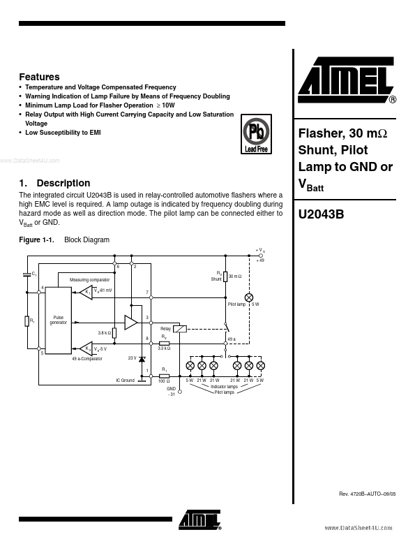
The integrated circuit U2043B is used in relay-controlled automotive flashers where a high EMC level is required. A lamp outage is indicated by frequency doubling during hazard mode as well as direction mode. The pilot lamp can be connected either to VBatt or GND. Figure 1-1. Block Diagram
+VS + 49 6 C1 Measuring parator 4 K 1 V 6-81 m V 7 Pilot lamp Pulse generator 3.8 k Ω 8 K 3 V 6-5 V 49 a-parator 23 V 1 IC Ground R1 100 Ω GND
- 31 5 W 21 W 21 W 21 W Indicator lamps Pilot lamps 21 W 5 W 3 Relay R2 3.3 k Ω 49 a 5W 2 R3 Shunt 30 m Ω
Flasher, 30 mΩ Shunt, Pilot Lamp to GND or VBatt U2043B
R1
Rev. 4720B- AUTO- 09/05
2. Pin Configuration
Figure 2-1. Pinning DIP8/SO8
1 2
8 7
VS REL
..
LD VS OSC
3 4 6 5
Table 2-1.
Pin 1 2 3 4 5 6 7 8
Pin Description
Symbol GND VS REL OSC OSC VS LD SI Function IC ground Supply voltage VS Relay driver C1 Oscillator R1 Oscillator Supply voltage VS Lamp failure detection Start input (49a)
4720B- AUTO- 09/05
3. Functional Description
3.1 GND (Pin 1)
The integrated circuit is protected against damage via resistor R4 to ground (- 31) in the case of battery reversal. An integrated protection circuit together with external resistances R2 and R4 limits the current pulses in the IC.
Supply Voltage, VS Power (Pin 2)
The arrangement of the supply connections to pin 2 must be so as to ensure that, on the connection printed circuit board (PCB), the resistance of VS to pin 6 is lower than that to pin 2.
.. 3.3 Relay
Control Output (Driver, Pin 3)
The relay control output is a high-side driver with a low saturation voltage and capable of driving a typical automotive relay with a minimum coil resistance of...