U4223B
U4223B is Time-Code Receiver with A/D Converter manufactured by Atmel.
Description
The U4223B is a bipolar integrated straight-through receiver circuit in the frequency range of 40 k Hz to 80 k Hz. The device is designed for radio-controlled clock applications.
Features
D Very low power consumption D Very high sensitivity D High selectivity by using two crystal filters D Power-down mode available D Only a few external ponents necessary D 4-bit digital output D AGC hold mode
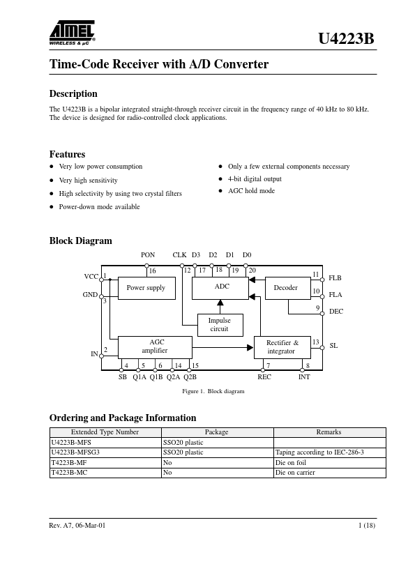
Block Diagram
PON VCC 1 GND 16 Power supply 3 9 Impulse circuit 2 4 AGC amplifier 5 6 14 15 Rectifier & integrator 7 REC 8 INT 13 SL CLK D3 12 17 D2 18 ADC D1 19 D0 20 Decoder 11 10 FLB FLA DEC
SB Q1A Q1B Q2A Q2B
Figure 1. Block diagram
Ordering and Package Information
Extended Type Number U4223B-MFS U4223B-MFSG3 T4223B-MF T4223B-MC Package SSO20 plastic SSO20 plastic No No Remarks Taping according to IEC-286-3 Die on foil Die on carrier
Rev. A7, 06-Mar-01
1 (18)
Pin Description
Pin VCC IN GND SB Q1A Q1B 1 2 3 4 5 20 19 18 17 16 D0 (LSB) D1 D2 D3 (MSB) PON Q2B Q2A SL CLK FLB 1 2 3 4 5 6 7 8 9 10 15 14 13 12 11 11 12 REC INT DEC FLA 7 8 9 10 13 14 15 16 17 18 19 20
Figure 2. Pinning
Symbol VCC IN GND SB Q1A Q1B REC INT DEC FLA FLB CLK SL Q2A Q2B PON D3 D2 D1 D0
Function Supply voltage Amplifier
- Input Ground Bandwidth control Crystal filter 1 Crystal filter 1 Rectifier output Integrator output Decoder input Lowpass filter Lowpass filter Clock input for ADC AGC hold mode Crystal filter 2 Crystal filter 2 Power ON/OFF control Data out MSB Data out Data out Data out LSB
A ferrite antenna is connected between IN and VCC. For high sensitivity, the Q factor of the antenna circuit should be as high as possible. Please note that a high Q factor requires temperature pensation of the resonant frequency in most cases. Specifications are valid for Q>30. An optimal signal-to-noise ratio will be achieved by a resonant resistance of 50 to 200 k W.
A resistor RSB is connected between SB and GND. It controls the bandwidth of the crystal filters....