AT-42085
AT-42085 is Up to 6 GHz Medium Power Silicon Bipolar Transistor manufactured by Agilent Technologies.
Description
Agilent’s AT-42085 is a general purpose NPN bipolar transistor that offers excellent high frequency performance. The AT-42085 is housed in a low cost .085" diameter plastic package. The 4 micron emitter-to-emitter pitch enables this transistor to be used in many different functions. The 20 emitter finger interdigitated geometry yields a medium sized transistor with impedances that are easy to match for low noise and medium power applications. Applications include use in wireless systems as an LNA, gain stage, buffer, oscillator, and mixer. An optimum noise match near 50Ω up to 1 GHz, makes this device easy to use as a low noise amplifier.
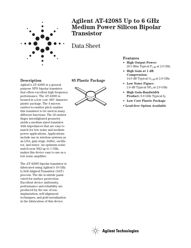
85 Plastic Package
The AT-42085 bipolar transistor is fabricated using Agilent’s 10 GHz f T Self-Aligned-Transistor (SAT) process. The die is nitride passivated for surface protection. Excellent device uniformity, performance and reliability are produced by the use of ionimplantation, self-alignment techniques, and gold metalization in the fabrication of this device.
Features
- High Output Power: 20.5 d Bm Typical P1 d B at 2.0 GHz
- High Gain at 1 d B pression: 14.0 d B Typical G1 d B at 2.0 GHz
- Low Noise Figure: 2.0 d B Typical NFO at 2.0 GHz
- High Gain-Bandwidth Product: 8.0 GHz Typical f T
- Low Cost Plastic Package
- Lead-free Option Available
AT-42085 Absolute Maximum Ratings
Symbol VEBO VCBO VCEO IC PT Tj TSTG
Parameter Emitter-Base Voltage Collector-Base Voltage Collector-Emitter Voltage Collector Current Power Dissipation [2,3] Junction Temperature Storage Temperature
Units V V V m A m W °C °C
Absolute Maximum[1]
1.5 20 12 80 500 150 -65 to 150
Thermal Resistance[2,4]: θjc = 130°C/W
Notes: 1. Permanent damage may occur if any of these limits are exceeded. 2. TCASE = 25°C. 3. Derate at 7.7 m W/°C for TC > 85°C. 4. See MEASUREMENTS section
“Thermal Resistance” for more information.
Electrical Specifications, TA = 25°C
Symbol
Parameters and Test Conditions
|S21E|2 Insertion Power Gain; VCE = 8 V, IC = 35...