HCPL-J312 Overview
Key Specifications
Package: DIP
Mount Type: Through Hole
Pins: 8
Operating Voltage: 30 V
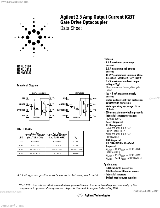
Representative HCPL-J312 image (package may vary by manufacturer)
Key Features
- 2.5 A maximum peak output current
- 2.0 A minimum peak output current
- 15 kV/µs minimum Common Mode Rejection (CMR) at VCM = 1500 V
- 0.5 V maximum low level output voltage (VOL) Eliminates need for negative gate drive
- ICC = 5 mA maximum supply current