A3951 Overview
Key Specifications
Package: PDIP
Operating Voltage: 5 V
Max Voltage (typical range): 5.5 V
Min Voltage (typical range): 4.5 V
| Part | A3951 |
|---|---|
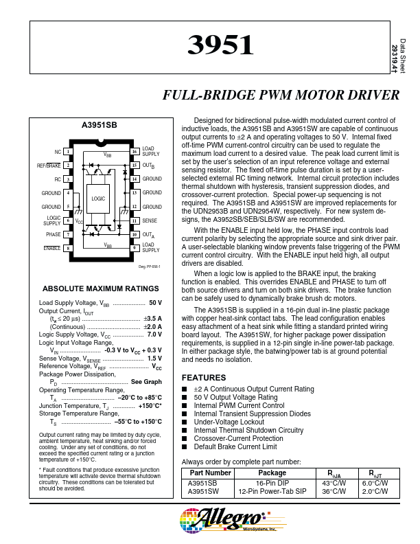
| Description | FULL-BRIDGE PWM MOTOR DRIVER |
| Manufacturer | Allegro MicroSystems |
| Size | 201.73 KB |
Package: PDIP
Operating Voltage: 5 V
Max Voltage (typical range): 5.5 V
Min Voltage (typical range): 4.5 V
| Seller | Inventory | Price Breaks | Buy |
|---|---|---|---|
| Win Source | 20 | - | View Offer |
| SHENGYU ELECTRONICS | 14240 | 1+ : 2.1439 USD 10+ : 2.101 USD 100+ : 2.04 USD 1000+ : 1.97 USD |
View Offer |
| Part Number | Manufacturer | Description |
|---|---|---|
| A3952 | Allegro MicroSystems | FULL-BRIDGE PWM MOTOR DRIVER |
| A3952SB | Allegro MicroSystems | FULL-BRIDGE PWM MOTOR DRIVER |
| A3952SW | Allegro MicroSystems | FULL-BRIDGE PWM MOTOR DRIVER |
| A3957 | Allegro MicroSystems | FULL-BRIDGE PWM MICROSTEPPING MOTOR DRIVER |