ABSOLUTE MAXIMUM RATINGS
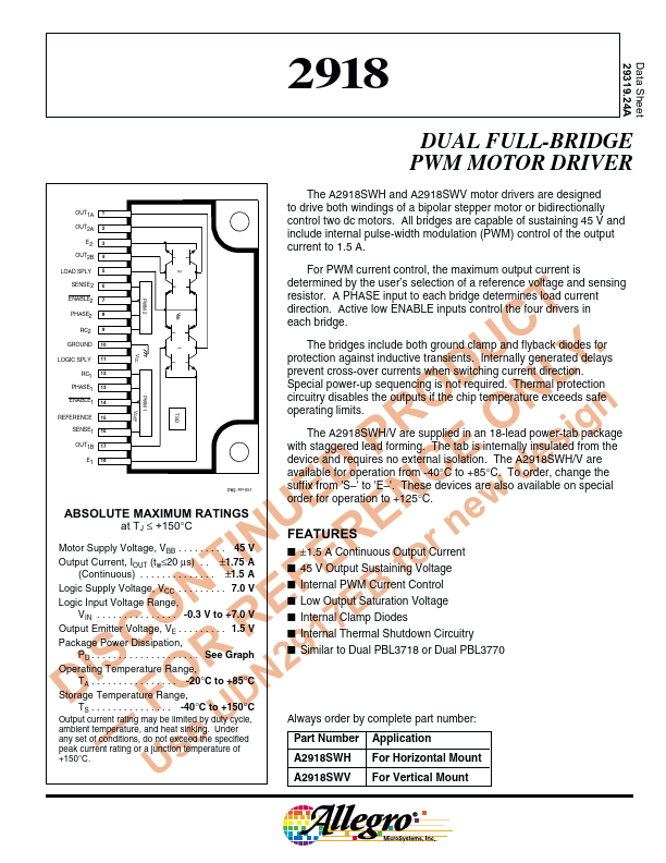
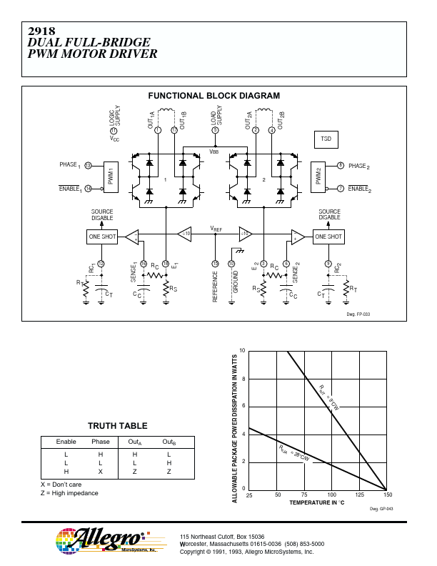
e at TJ ≤ +150°C U E n Motor Supply Voltage, VBB . . . . . . . . . 45 V IN R r Output Current, IOUT (tw≤20 µs) . . ±1.75 A T E fo (Continuous) . . . . . . . . . . . . . . ±1.5 A Logic Supply Voltage, VCC . . . . . . . . . 7.0 V N F B Logic Input Voltage Range, E E VIN . . . . . . . . . . . . . . . -0.3 V to +7.0 V O R 7 Output Emitter Voltage, VE . . . . . . . . . 1.5 V C 1 Package Power Dissipation, PD . . . . . . . . . . . . . . . . . . . . See Graph IS R 9 Operating Temperature Range, 2 TA . . . . . . . . . . . . . . . . -20°C to +85°C D O N Storage Temperature Range, F D TS . . . . . . . . . . . . . . . -40°C to +150°C Output current rating may be limited by duty cycle, U ambient temperature, and heat sinking. Under any set of conditions, do not exceed the specified — e peak current rating or a junction temperature of Us +150°C. determined by the user’s selection of a reference voltage and sensing resistor. A PHASE input to each bridge determines load current direction. Allegro MicroSystems