Allegro MicroSystems A6850
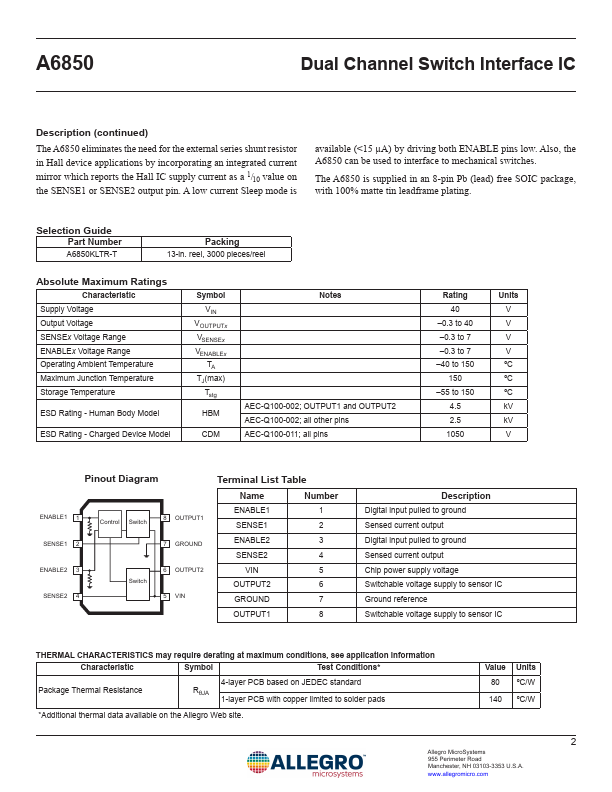
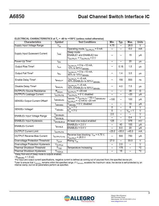
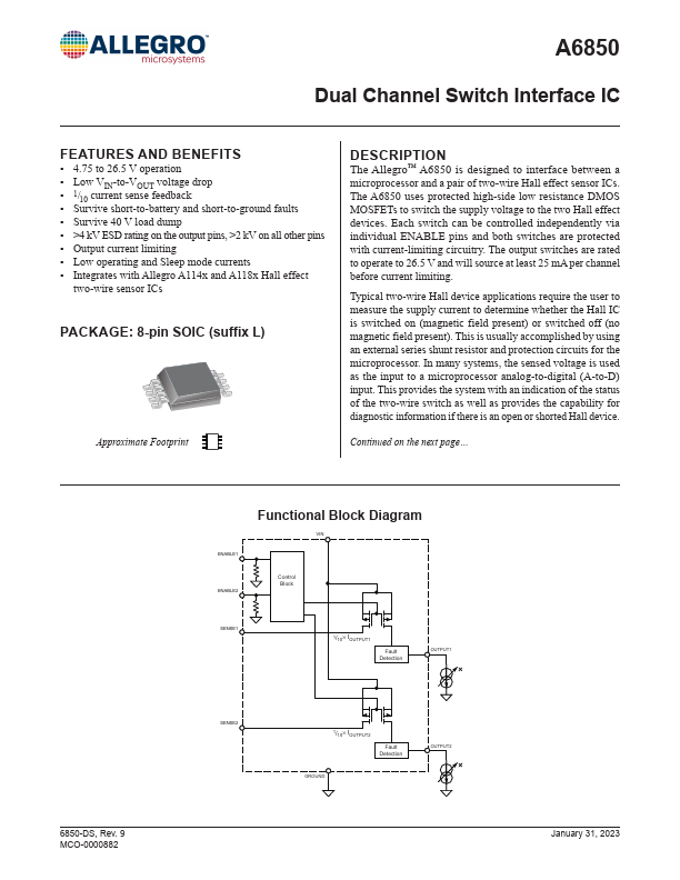
A6850 is designed to interface between a microprocessor and a pair of two-wire Hall effect sensor ICs. The A6850 uses protected high-side low resistance DMOS MOSFETs to switch the supply voltage to the two Hall effect devices. Each switch can be controlled independently via individual ENABLE pins and both switches are protected with current-limiting circuitry.| Part No. | A6850 |
|---|---|
| Datasheet | A6850 Download |
| Manufacturer |  Allegro MicroSystems |
| Description | Dual-Channel Switch Interface |
| Buy | Stock & Price |
FEATURES AND BENEFITS
● 4.75 to 26.5 V operation● Low VIN-to-VOUT voltage drop
● 1/10 current sense feedback
● Survive short-to-battery and short-to-ground faults
● Survive 40 V load dump
● >4 kV ESD rating on the output pins, >2 kV on all other pins
● Output current limiting
● Low operating and Sleep mode currents
● Integrates with Allegro A114x and A118x Hall effect two-wire sensor ICs PACKAGE: 8-pin SOIC (suffix L) Approximate Footprint
DESCRIPTION
The Allegro™ The output switches are rated to operate to 26.5 V and will source at least 25 mA per channel before current limiting. Typical two-wire Hall device applications require the user to measure the supply current to determine whether the Hall IC is switched on (magnetic field present) or switched off (no magnetic field present). This is usually accomplished by using an external series shunt resistor and protection circuits for the microprocessor. In many systems, the sensed voltage is used as the input to a microprocessor analog-to-digital (A-to-D) input.