• Part: AMT49701
  • Description: Quad DMOS Full-Bridge PWM Motor Driver
  • Manufacturer: Allegro MicroSystems
  • Size: 694.69 KB
Download AMT49701 Datasheet PDF
Allegro MicroSystems
AMT49701
AMT49701 is Quad DMOS Full-Bridge PWM Motor Driver manufactured by Allegro MicroSystems.
FEATURES AND BENEFITS - 18 V output rating - 4 full bridges - Dual stepper motor driver - High-current outputs - 3.3 and 5 V patible logic - Synchronous rectification - Internal undervoltage lockout (UVLO) - Thermal shutdown circuitry - Crossover-current protection - Overcurrent protection - Low-profile QFN package PACKAGE: Package EV, 36-pin QFN 0.90 mm nominal height with exposed thermal pad Not to scale DESCRIPTION 
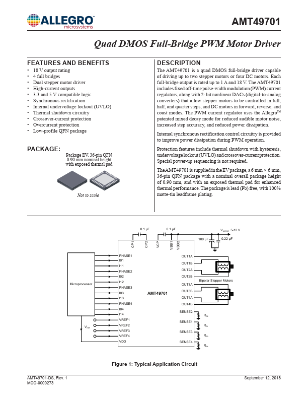
The AMT49701 is a quad DMOS full-bridge driver capable of driving up to two stepper motors or four DC motors. Each full-bridge output is rated up to 1 A and 18 V. The AMT49701 includes fixed off-time pulse-width modulation (PWM) current regulators, along with 2- bit nonlinear DACs (digital-to-analog converters) that allow stepper motors to be controlled in full, half, and quarter steps, and DC motors in forward, reverse, and coast modes. The PWM current regulator uses the Allegro™ patented mixed decay mode for reduced audible motor noise, increased step accuracy, and reduced power dissipation. Internal synchronous rectification control circuitry is provided to improve power dissipation during PWM operation. Protection features include thermal shutdown with hysteresis, undervoltage lockout (UVLO) and crossover-current protection. Special power-up sequencing is not required. The AMT49701 is supplied in the EV package, a 6  mm  ×  6  mm, 36-pin QFN package with a nominal overall package height of 0.90 mm, and with an exposed thermal pad for enhanced thermal performance. The package is lead (Pb) free, with 100% matte-tin leadframe plating. Microprocessor VREF AMT49701-DS, Rev. 1 MCO-0000273 0.1 µF 0.1 µF 100 µF VMOTOR 5-12 V 0.22 µF CP1 CP2 VCP VBB1 VBB2 PHASE1 I01 I11 PHASE2 I02 I12 PHASE3 I03 I13 PHASE4 I04 I14 VREF1 VREF2 VREF3 VREF4 VDD OUT1A OUT1B OUT2A OUT2B OUT3A OUT3B OUT4A OUT4B SENSE2 SENSE1 SENSE3 SENSE4 Bipolar Stepper Motors RS2 RS1 RS3 RS4 Figure 1: Typical Application Circuit September 12,...