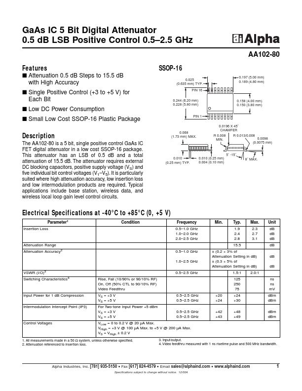
FEATURES
s Attenuation 0.5 dB Steps to 15.5 dB with High Accuracy s Single Positive Control (+3 to +5 V) for Each Bit s Low DC Power Consumption s Small Low Cost SSOP-16 Plastic Package SSOP-16 0.025 (0.635 mm) TYP. PIN 16 0.244 (6.20 mm) 0.228 (5.80 mm) PIN 1 0.0196 X 45˚ CHAMFER R 0.008 MIN. R 0.013/0.008 0.0098 (0.0075 mm) 0.158 (4.00 mm) 0.150 (3.80 mm) 0.197 (5.00 mm) 0.189 (4.80 mm) DESCRIPTION
It is particularly suited where high attenuation accuracy, low insertion loss and low intermodulation products are required. Typical applications include base station, wireless data, and wireless local loop gain level control circuits. 0.068 (1.73 mm) MAX. 5˚ -15˚ 0.010 (0.25 mm) TYP. 0.010 (0.25 mm) 0.004 (0.10 mm) 8˚ MAX. ELECTRICAL SPECIFICATIONS
at -40°C to +85°C (0, +5 V) Parameter1 Insertion Loss Condition Frequency 0.5–1.0 GHz 1.0–2.0 GHz 2.0–2.5 GHz 0.5–1.0 GHz 1.0–2.5 GHz VSWR (I/O)3 Switching Characteristics4 Rise, Fall (10/90% or 90/10% RF) On, Off (50% CTL to 90/10% RF) Video Feedthru VS = +3 V VS = +5 V For Two-tone Input Power +5 dBm VS = +3 V VS = +5 V 0.5–2.5 GHz 0.5–2.5 GHz 0.5–2.5 GHz 0.5–2.5 GHz +20 +24 +42 +43 0.5–2. Alpha Industries