AP1605
AP1605 is PWM/PFM Dual-mode Step-Down Switching Regulator manufactured by Anachip.
Features
- Low current consumption: In operation: 100µA max. Power off: 2µA max.
- Input voltage: 2.5V to 7V. Adjustable version (+2.5%)
- PWM/PFM dual Mode
- Oscillation frequency: 300KHz (Typ.)
- With a power-off function.
- Built-in internal SW P-channel MOS
- SOP-8L/TSSOP-8L Package.
- General Description
AP1605 consists of CMOS step-down switching regulator with PWM/PFM dual mode control. These devices include a reference voltage source, oscillation circuit, error amplifier, internal PMOS and etc. AP1605 provides low-ripple power, high efficiency, and excellent transient characteristics. The PWM/PFM control circuit is able to very the duty ratio linearly 0%~0.25% (PFM) and 25%~100% (PWM). With the addition of an internal P-channel Power MOS, a coil, capacitors, and a diode connected externally, these ICs can function as step-down switching regulators. They serve as ideal power supply units for portable devices when coupled with the SOP- 8L mini-package, providing such outstanding features as low current consumption. Since this converter can acmodate an input voltage of up to 7V, it is also ideal when operating via an AC adapter.
- Applications
- On-board power supplies of battery devices for portable telephones, electronic notebooks, PDA, and other hand-held sets.
- Power supplies for audio equipment, including portable CD players and headphone stereo equipment.
- Fixed voltage power supply for cameras, video equipment and munications equipment.
- Power supplies for microputers.
- Conversion from four Ni-H or Ni-Cd cells or two lithium-ion cells to 3.3V/3V.
- Conversion of AC adapter input to 5V/3V.
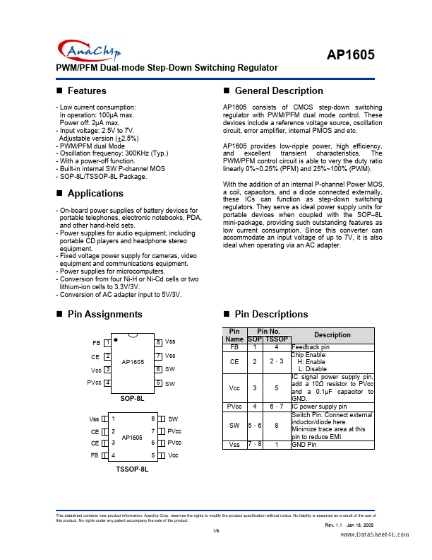
- Pin Assignments
FB CE 1 2 AP1605 6 SW 5 SW 8 Vss 7 Vss
- Pin Descriptions
Pin Pin No. Name SOP TSSOP
FB CE 1 2 4 2、3
Description
Feedback pin Chip Enable: H: Enable L: Disable IC signal power supply pin, add a 10Ω resistor to PVcc and a 0.1µF capacitor to GND. IC power supply pin Switch Pin. Connect external inductor/diode here. Minimize trace area at this...