Datasheet4U Logo Datasheet4U.com

AD75019 - 16 x 16 Crosspoint Switch Array

General Description

The AD75019 contains 256 analog switches in a 16 × 16 array.

Any of the X or Y pins may serve as an input or output.

Any or all of the X terminals may be programmed to connect to any or all of the Y terminals.

Key Features

  • 256 Switches in a 16 ؋ 16 Array Wide Signal Range: to Supply Rails of 24 V or ؎12 V Low On-Resistance: 200 ⍀ Typ TTL/CMOS/Microprocessor-Compatible Control Lines Serial Input Simplifies Interface Serial Output Allows Cascading for More Channels Low Power Consumption: 2 mW Quiescent Compact 44-Lead PLCC X0 Y0 16 ؋ 16 Crosspoint Switch Array AD75019.

📥 Download Datasheet

Full PDF Text Transcription (Reference)

The following content is an automatically extracted verbatim text from the original manufacturer datasheet and is provided for reference purposes only.

View original datasheet text
a FEATURES 256 Switches in a 16 ؋ 16 Array Wide Signal Range: to Supply Rails of 24 V or ؎12 V Low On-Resistance: 200 ⍀ Typ TTL/CMOS/Microprocessor-Compatible Control Lines Serial Input Simplifies Interface Serial Output Allows Cascading for More Channels Low Power Consumption: 2 mW Quiescent Compact 44-Lead PLCC X0 Y0 16 ؋ 16 Crosspoint Switch Array AD75019 
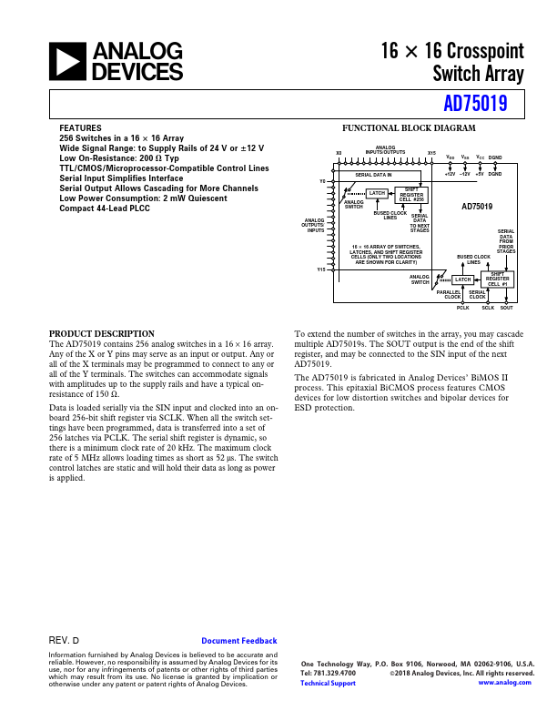
FUNCTIONAL BLOCK DIAGRAM ANALOG INPUTS/OUTPUTS X15 VDD VSS VCC DGND SERIAL DATA IN SHIFT REGISTER CELL #256 +12V –12V +5V DGND LATCH ANALOG SWITCH ANALOG OUTPUTS/ INPUTS AD75019 BUSED CLOCK LINES SERIAL DATA TO NEXT STAGES 16 ؋ 16 ARRAY OF SWITCHES, LATCHES, AND SHIFT REGISTER CELLS (ONLY TWO LOCATIONS ARE SHOWN FOR CLARITY) Y15 ANALOG SWITCH SERIAL DATA FROM PRIOR STAGES BUSED CLOCK LINES SHIFT REGISTER CELL #1 LATCH PARALLEL