AD8333
AD8333 is Dual I/Q Demodulator and Phase Shifter manufactured by Analog Devices.
FEATURES
Dual integrated I/Q demodulator 16 phase select options on each output (22.5° per step) Quadrature demodulation accuracy
Phase accuracy: ±0.1° Amplitude balance: ±0.05 d B Bandwidth 4 × LO: 10 k Hz to 200 MHz RF: dc to 50 MHz Baseband: determined by external filtering Output dynamic range: 159 d B/Hz LO drive > 0 d Bm (50 Ω); 4 × LO > 1 MHz Supply: ±5 V Power consumption: 190 m W/channel (380 m W total) Power-down
APPLICATIONS
Medical imaging (CW ultrasound beamforming) Phased array systems (radar and adaptive antennas) munication receivers
GENERAL DESCRIPTION
The AD83331 is a dual phase-shifter and I/Q demodulator that enables coherent summing and phase alignment of multiple analog data channels. It is the first solid-state device suitable for beamformer circuits, such as those used in high performance medical ultrasound equipment featuring CW Doppler. The RF inputs interface directly with the outputs of the dual-channel, low noise preamplifiers included in the AD8332.
A divide-by-4 circuit generates the internal 0° and 90° phases of the local oscillator (LO) that drive the mixers of a pair of matched I/Q demodulators.
The AD8333 can be applied as a major element in analog beamformer circuits in medical ultrasound equipment.
The AD8333 features an asynchronous reset pin. When used in arrays, the reset pin sets all the LO dividers in the same state. Sixteen discrete phase rotations in 22.5° increments can be selected independently for each channel. For example, if Channel 1 is used as a reference and the RF signal applied to Channel 2 has an I/Q phase lead of 45°, Channel 2 can be phase aligned with Channel 1 by choosing the correct code.
1 Protected by US Patent 7,760,833.
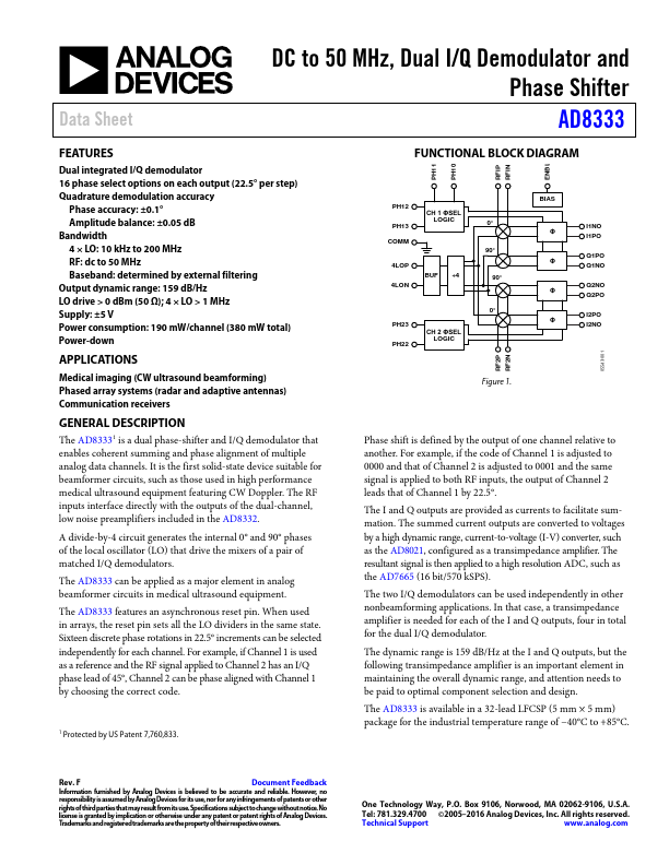
FUNCTIONAL BLOCK DIAGRAM
PH11 PH10 RFIP RFIN ENBL
PH12 PH13 M
CH 1 ΦSEL LOGIC
4LOP 4LON
BUF ÷4
PH23 PH22
CH 2 ΦSEL LOGIC
0° 90°
90° 0°
BIAS Φ Φ Φ Φ
I1NO I1PO
Q1PO Q1NO
Q2NO Q2PO
I2PO I2NO
RF2P RF2N
05543-001
Figure 1.
Phase shift is defined by the output of one channel relative...