Datasheet Summary
a
Features
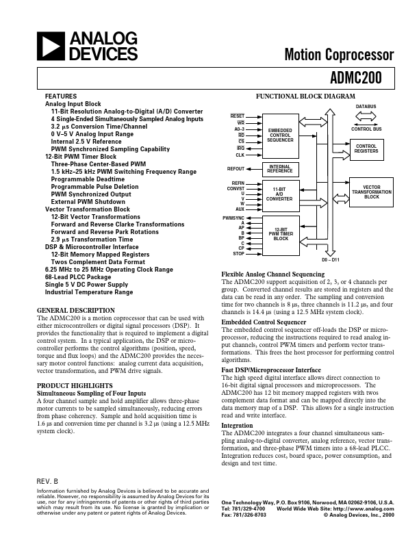
Analog Input Block 11-Bit Resolution Analog-to-Digital (A/D) Converter 4 Single-Ended Simultaneously Sampled Analog Inputs 3.2 s Conversion Time/Channel 0 V- 5 V Analog Input Range Internal 2.5 V Reference PWM Synchronized Sampling Capability 12-Bit PWM Timer Block Three-Phase Center-Based PWM 1.5 kHz- 25 kHz PWM Switching Frequency Range Programmable Deadtime Programmable Pulse Deletion PWM Synchronized Output External PWM Shutdown Vector Transformation Block 12-Bit Vector Transformations Forward and Reverse Clarke Transformations Forward and Reverse Park Rotations 2.9 s Transformation Time DSP & Microcontroller Interface 12-Bit Memory Mapped Registers Twos plement Data...