ADuM5211
ADuM5211 is Dual-Channel Isolators manufactured by Analog Devices.
- Part of the ADuM5210 comparator family.
- Part of the ADuM5210 comparator family.
Data Sheet
Dual-Channel Isolators with Integrated DC-to-DC Converters ADu M5210/ADu M5211/ADu M5212
Features iso Power integrated, isolated dc-to-dc converter Regulated 3.15 V to 5.25 V output Up to 150 m W output power Dual dc-to-100 Mbps (NRZ) signal isolation channels Soft start power supply 20-lead SSOP package with 5.3 mm creepage Supports SPI up to 15 MHz High temperature operation: 105°C High mon-mode transient immunity: >25 k V/µs Safety and regulatory approvals
UL recognition (pending) 2500 V rms for 1 minute per UL 1577
CSA ponent Acceptance Notice #5A (pending) VDE certificate of conformity (pending)
DIN V VDE V 0884-10 (VDE V 0884-10):2006-12 VIORM = 560 V peak
APPLICATIONS
RS-232 transceivers Power supply start-up bias and gate drives Isolated sensor interfaces Industrial PLCs
GENERAL DESCRIPTION
The ADu M5210/ADu M5211/ADu M52121 are dual-channel digital isolators with iso Power®, an integrated, isolated dc-to-dc converter. Based on the Analog Devices, Inc., i Coupler® technology, the dc-todc converter provides regulated, isolated power that is adjustable between 3.15 V and 5.25 V. Input supply voltages can range from slightly below the required output to significantly higher. Popular voltage binations and their associated power levels are shown in Table 1.
The ADu M5210/ADu M5211/ADu M5212 eliminate the need for a separate, isolated dc-to-dc converter in low power, isolated designs. The i Coupler chip-scale transformer technology is used for isolated logic signals and for the magnetic ponents of the dcto-dc converter. The result is a small form factor, total isolation solution. iso Power uses high frequency switching elements to transfer power through its transformer. Take special care during printed circuit board (PCB) layout to meet emissions standards. See the AN-0971 Application Note for board layout remendations.
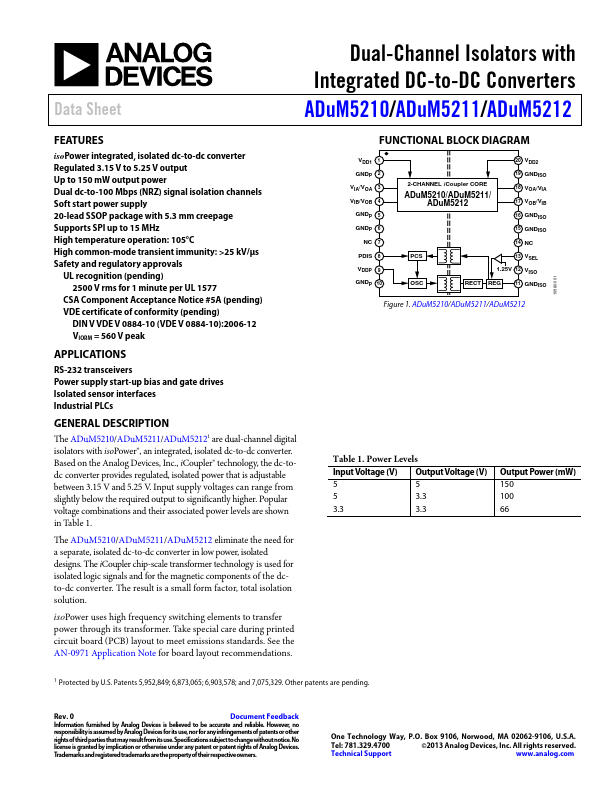
FUNCTIONAL BLOCK DIAGRAM
VDD1 1 GNDP 2 VIA/VOA 3 VIB/VOB 4 GNDP 5 GNDP 6
NC 7 PDIS 8 VDDP 9 GNDP 10
20 VDD2
2-CHANNEL i Coupler...