APPLICATIONS
FEATURES
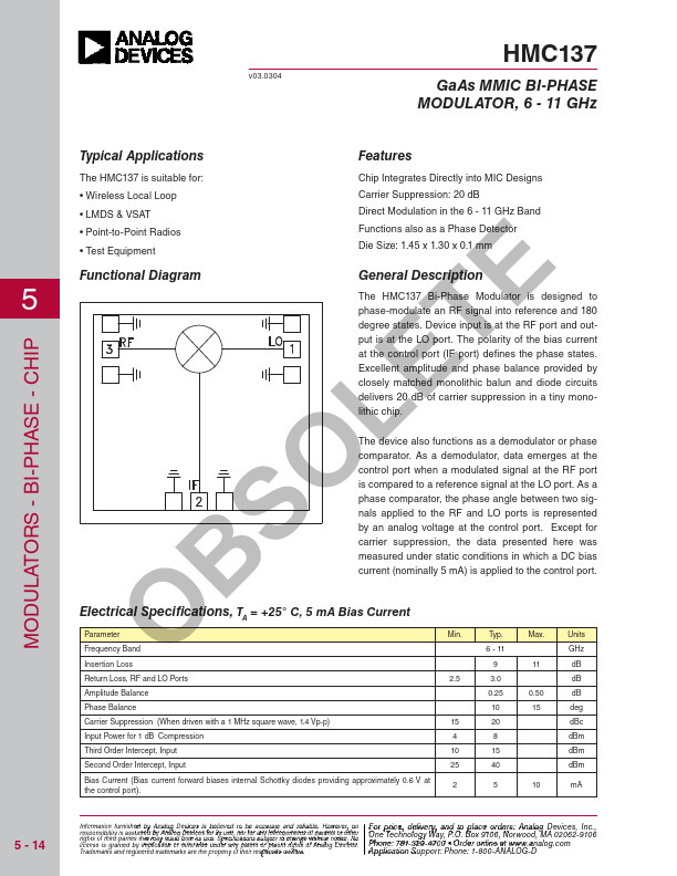
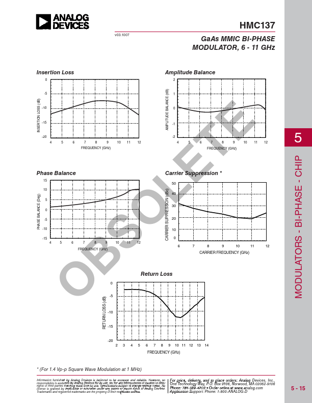
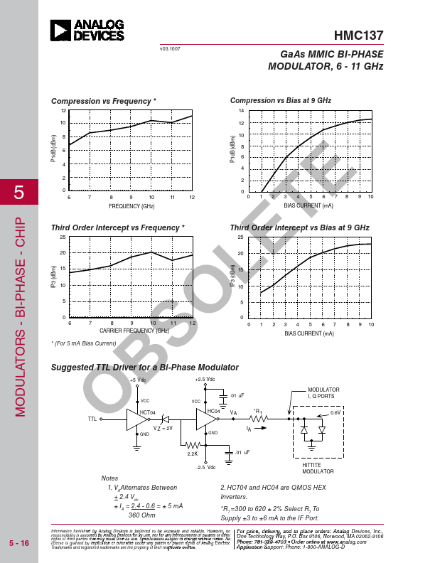
Device input is at the RF port and output is at the LO port. Excellent amplitude and phase balance provided by closely matched monolithic balun and diode circuits delivers 20 dB of carrier suppression in a tiny monolithic chip. As a demodulator, data emerges at the control port when a modulated signal at the RF port is compared to a reference signal at the LO port. As a phase comparator, the phase angle between two signals applied to the RF and LO ports is represented by an analog voltage at the control port. Except for carrier suppression, the data presented here was measured under static conditions in which a DC bias current (nominally 5 mA) is applied to the control port. B ELECTRICAL SPECIFICATIONS
, TA = +25° C, 5 mA Bias Current Parameter O Frequency Band Min. Typ. Max. Units 6 - 11 GHz Insertion Loss 9 11 dB Return Loss, RF and LO Ports 2.5 3.0 dB Amplitude Balance 0.25 0.50 dB Phase Balance 10 15 deg Carrier Suppression (When driven with a 1 MHz square wave... Analog Devices