Analog Devices HMC424
The HMC424 is ideal for: 0.5 dB LSB Steps to 31.5 dB • Fiber Optics & Broadband Telecom Single Control Line Per Bit • Microwave Radio & VSAT ±0.5 dB Typical Bit Error • Military Radios, Radar & ECM Die Size: 1.45 x 0.85 x 0.1 mm • Space Applications LETE Functional Diagram General Description The HMC424 die is a broadband 6-bit GaAs IC digital attenuator MMIC chip. The attenuator bit values are 0.5 (LSB), 1, 2, 4, 8, and 16 dB for a total attenuation of 31.5 dB.
| Part No. |
HMC424 |
| Datasheet |
HMC424
Download
|
| Manufacturer |
 Analog Devices |
| Description |
0.5dB LSB GaAs MMIC |
| Buy |
Stock & Price
|
APPLICATIONS
FEATURES
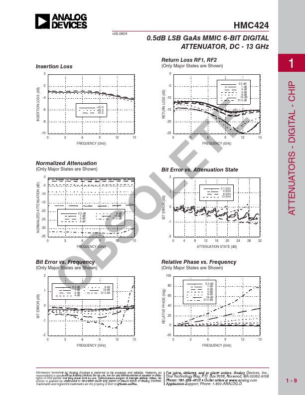
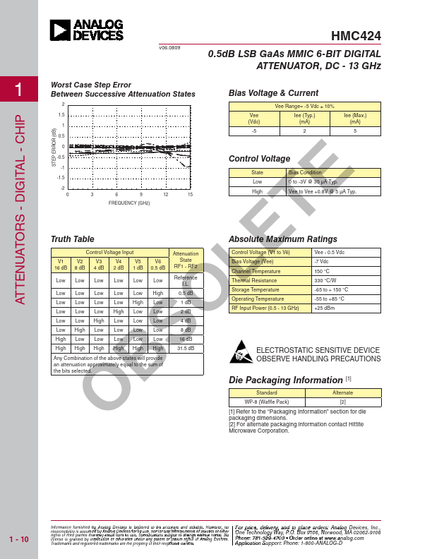
Covering DC to 13 GHz, the insertion loss is less then 4 dB typical. Attenuation accuracy is excellent at ± 0.5 dB typical step error with an IIP3 of +32 dBm. Six control voltage inputs, toggled between 0 and -5V, are used to select each attenuation state. A single Vee bias of -5V allows operation at frequencies down to DC. BSO ELECTRICAL SPECIFICATIONS
, TA = +25° C, With Vee = -5V & VCTL = 0/-5V Parameter Frequency (GHz) Min. Typ. O Insertion Loss DC - 8.0 GHz 3.0 8.0 - 13.0 GHz 4.0 Max. 3.8 4.6 Units dB dB Attenuation Range DC - 13.0 GHz 31.5 dB Return Loss (RF1 & RF2, All Atten. States) Attenuation Accuracy: (Referenced to Insertion Loss) Input Power for 0.1 dB Compression Input Third Order Intercept Point (Two-Tone Input Power= 0 dBm Each Tone) Switching Characteristics DC - 8.0 GHz 8 12 dB 8.0 - 13.0 GHz 11 15 dB 0.5 - 7.5 dB States 8 - 31.5 dB States REF State All Other States DC - 13.0 GHz DC - 13.0 GHz 1.0 - 13.0 Ghz 1.0 - 13.0 Ghz DC - 13.0 GHz ± 0.3 + 4% of Atten.