APPLICATIONS
FEATURES
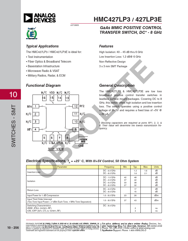
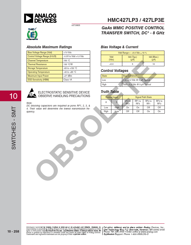
Covering DC to 8 GHz, this switch offers high isolation and low insertion loss. * Blocking capacitors are required at ports RF1, 2, 3, & 4. Their value will determine the lowest transmission frequency. SO ELECTRICAL SPECIFICATIONS
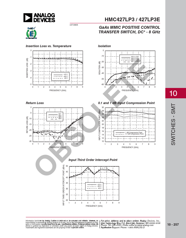
, TA = +25° C, With 0/+5V Control, 50 Ohm System BParameter Frequency Min. Typ. Max. Units Insertion Loss DC - 6.0 GHz DC - 8.0 GHz 1.2 1.6 dB 1.6 2.1 dB O DC - 1.0 GHz 42 48 dB DC - 2.0 GHz 37 42 dB Isolation DC - 6.0 GHz 33 38 dB DC - 8.0 GHz 27 32 dB Return Loss DC - 6.0 GHz 17 dB DC - 8.0 GHz 15 dB Input Power for 1 dB Compression 1.0 - 8.0 GHz 23 26 dBm Input Third Order Intercept (Two-Tone Input Power= +7 dBm Each Tone, 1 MHz Tone Separation) 1.0 - 8.0 GHz 37 43 dBm Switching Characteristics tRISE, tFALL (10/90% RF) tON, tOFF (50% CTL to 10/90% RF) DC - 8.0 GHz 2 ns 4 ns 10 - 256 Information furnisheFd obyr ApnrailocgeD,edviceeslivisebreylie,veadntdo bteoacpcularacteeanod rrdelieabrlse.,Hpowleevaers, eno coFnotrapcritcHe, idtteitlie... Analog Devices