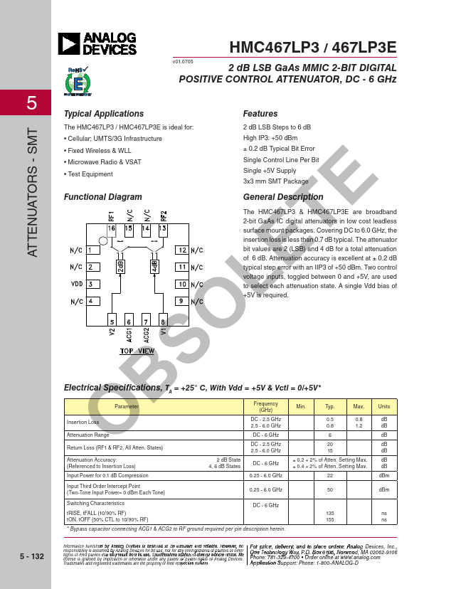
APPLICATIONS
FEATURES
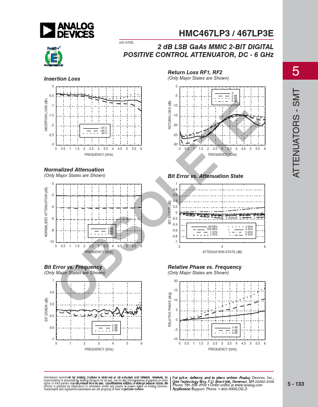
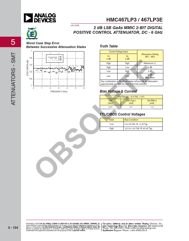
Covering DC to 6.0 GHz, the insertion loss is less than 0.7 dB typical. Attenuation accuracy is excellent at ± 0.2 dB typical step error with an IIP3 of +50 dBm. Two control voltage inputs, toggled between 0 and +5V, are used to select each attenuation state. A single Vdd bias of +5V is required. SOL ELECTRICAL SPECIFICATIONS
, TA = +25° C, With Vdd = +5V & Vctl = 0/+5V* B Parameter Insertion Loss O Attenuation Range Frequency (GHz) Min. Typ. DC - 2.5 GHz 0.5 2.5 - 6.0 GHz 0.8 DC - 6 GHz 6 Max. 0.8 1.2 Units dB dB dB Return Loss (RF1 & RF2, All Atten. States) DC - 2.5 GHz 20 dB 2.5 - 6.0 GHz 15 dB Attenuation Accuracy: (Referenced to Insertion Loss) 2 dB State ± 0.2 + 2% of Atten. Setting Max. dB 4, 6 dB States DC - 6 GHz ± 0.4 + 2% of Atten. Setting Max. dB Input Power for 0.1 dB Compression 0.25 - 6.0 GHz 22 dBm Input Third Order Intercept Point (Two-Tone Input Power= 0 dBm Each Tone) 0.25 - 6.0 GHz 50 dBm Switching Characteristics tRISE, tFALL (10/90% RF) tON, tOFF (50% CTL to 10/90% RF) DC - 6 GHz 135 ns 155 ns * Bypass capacitor connecting ACG1 & ACG2 to RF ground required per pin description herein. Analog Devices