FEATURES
PIN CONFIGURATIONS Low noise: 80 nV p-p (0.1 Hz to 10 Hz), 3 nV/√Hz Low drift: 0.2 µV/°C High speed: 2.8 V/µs slew rate, 8 MHz gain bandwidth Low VOS: 10 µV CMRR: 126 dB at VCM of ±11 V High open-loop gain: 1.8 million Available in die form GENERAL DESCRIPTION
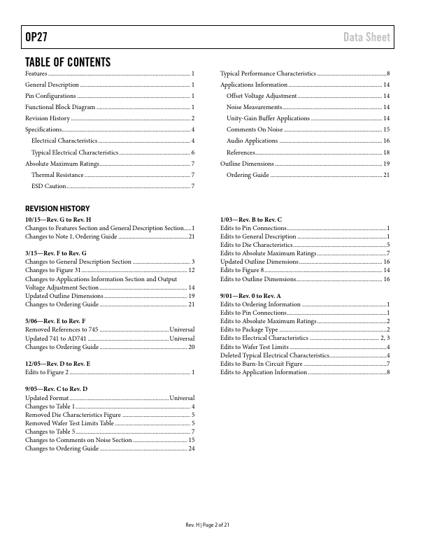
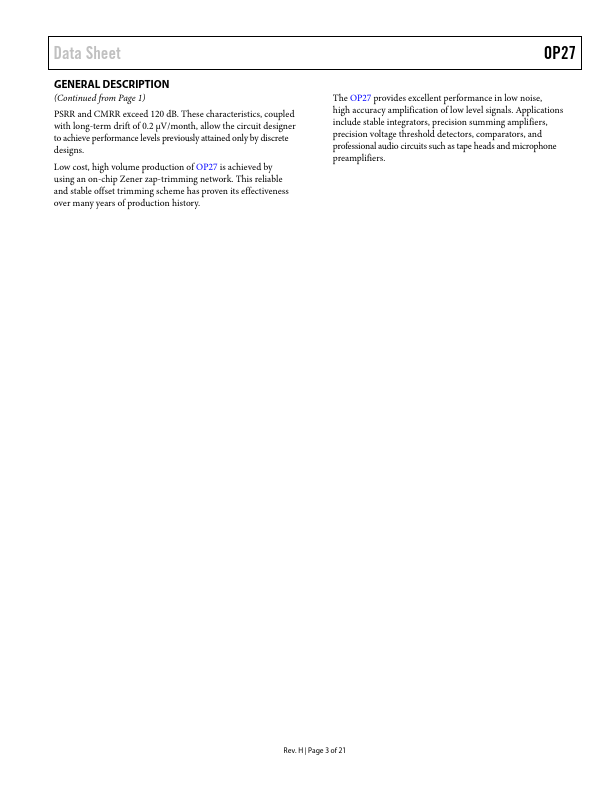
Low noise, en = 3.5 nV/√Hz, at 10 Hz, a low 1/f noise corner frequency of 2.7 Hz, and high gain (1.8 million), allow accurate high-gain amplification of low-level signals. A gain bandwidth product of 8 MHz and a 2.8 V/µs slew rate provide excellent dynamic accuracy in high speed, data-acquisition systems. BAL BAL 1 –IN 2 OP27 V+ OUT +IN 3 NC 00317-001 4V– (CASE) NC = NO CONNECT Figure 1. 8-Lead TO-99 (J-Suffix) VOS TRIM 1 –IN 2 +IN 3 V– 4 OP27 8 VOS TRIM 7 V+ 6 OUT 5 NC 00317-002 NC = NO CONNECT Figure 2. 8-Lead CERDIP – Glass Hermetic Seal (Z-Suffix), 8-Lead PDIP (P-Suffix), and 8-Lead SOIC (S-Suffix) A low input bias current of ±10 nA is achieved by use of a bias current cancellation circuit. Over the military temperature range, this circuit typically holds IB and IOS to ±20 nA and 15 nA, respectively. Analog Devices