FEATURES
0.01% THD at +10 dBV In/Out 100 dB VCA Dynamic Range Low VCA Control Feedthrough 100 dB Level Detection Range Log/Antilog Control Paths Low External Component Count APPLICATIONS
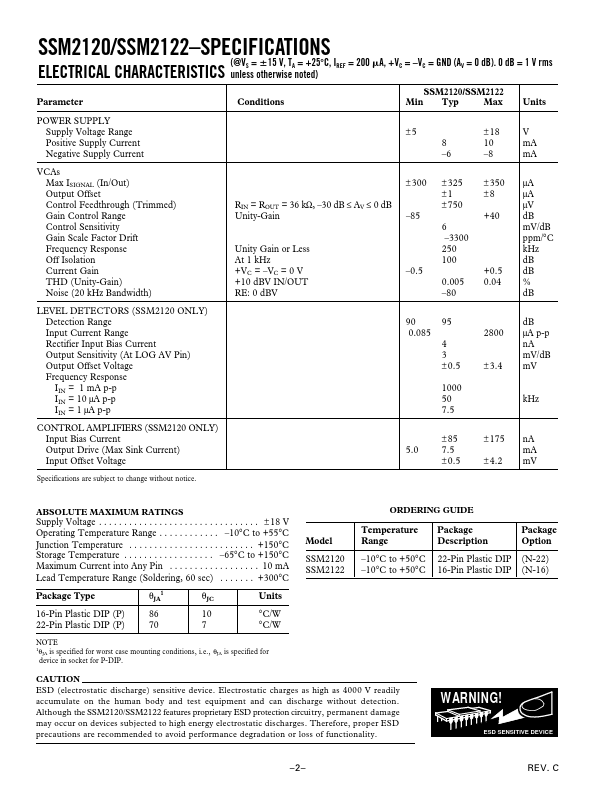
Compressors Expanders Limiters AGC Circuits Voltage-Controlled Filters Noise Reduction Systems Stereo Noise Gates Dynamic Range Processors/Dual VCA SSM2120/SSM2122 FUNCTIONAL BLOCK DIAGRAM V+ 36kΩ SIGNAL OUT CURRENT MIRRORS –VC +VC V+ V+ SIGNAL INPUT V+ 36kΩ IREF GENERAL DESCRIPTION
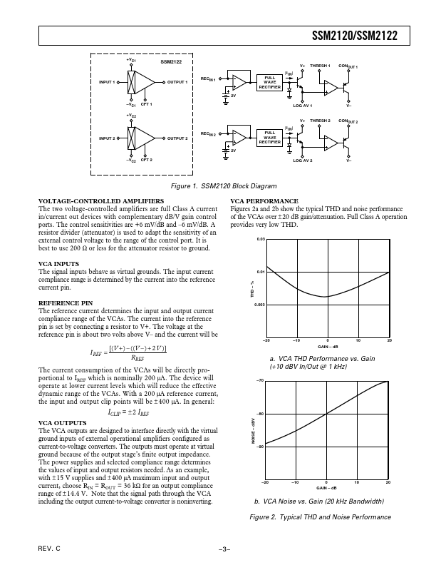
V– This allows the compression, expansion or limiting of ac signals, some of the primary applications for the SSM2120. PIN CONNECTIONS 22-Pin Plastic DIP (P Suffix) 16-Pin Plastic DIP (P Suffix) THRESH 1 1 LOG AV 1 2 CONOUT 1 3 SIGOUT 1 4 +VC1 5 CFT 1 6 22 GND 21 V+ 20 SIGOUT 2 19 +VC2 GND 1 SIGOUT 1 2 +VC1 3 CFT 1 4 16 GND 15 V+ 14 SIGOUT 2 SSM2120 18 CFT 2 13 +VC2 TOP VIEW –VC1 5 (Not to Scale) 12 CFT 2 11 –VC2 10 SIGIN 2 9 GND SSM2122 TOP VIEW 17 –VC2 –VC1 7 (Not to Scale) 16 SIGIN 2 15 RECIN 2 14 CONOUT 2 13 LOG AV 2 12 THRESH 2 SIGIN 1 6 IREF 7 V– 8 SIGIN 1 8 RECIN 1 9 IREF 10 V– 11 REV. Analog Devices