DESCRIPTION
AME5142AEEV Pin Number 1 Pin Name SW Pin DESCRIPTION
Power Switch input. Minimize the metal trace area connected to this pin to minimize EMI. Ground. Tie directly to ground plane. Output voltage feedback input. Connect the ground of the feedback network to an AGND (Analog Ground) plane which should be tied directly to the GND pin. Enable control input, active high. The enable pin is an active high control. Tie this pin above 1.5V to enable the device. Tie this pin below 0.4V to turn off the device. Analog and Power input. Input Supply Pin. Bypass this pin with a capacitor as close to the device as possible. 2 GND 3 FB 4 EN 5 IN Rev. A.01 3 AME, Inc. AME5142 n Pin DESCRIPTION
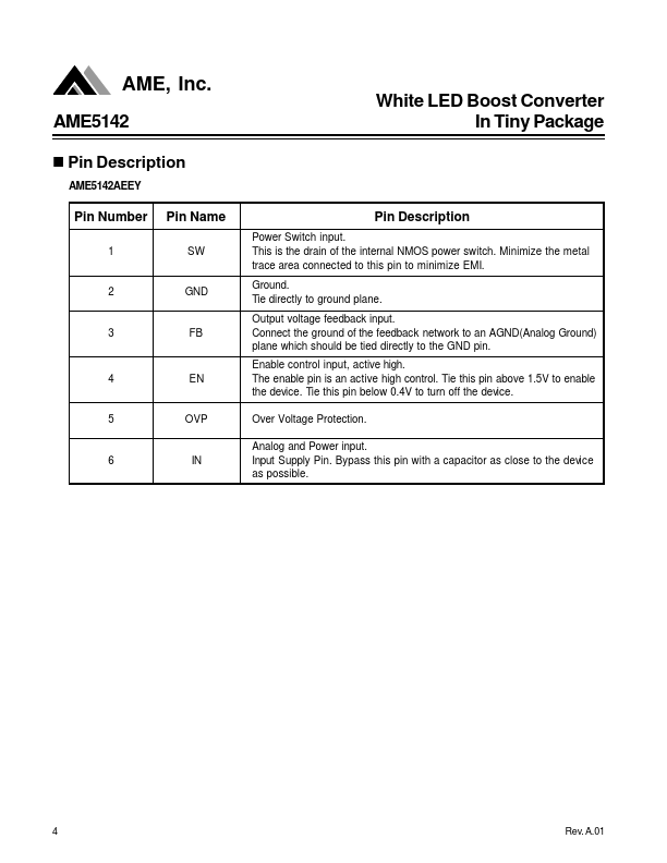
AME5142AEEY White LED Boost Converter In Tiny Package Pin Number 1 Pin Name SW Pin DESCRIPTION
Power Switch input. This is the drain of the internal NMOS power switch. Minimize the metal trace area connected to this pin to minimize EMI. Ground. Tie directly to ground plane. Output voltage feedback input. Analog Microelectronics