Apex Science RC242001
24-Characters x 2-Lines Display
| Part No. | RC242001 |
|---|---|
| Datasheet | RC242001 Download |
| Manufacturer | Apex Science |
| Description | 24-Characters x 2-Lines Display |
| Buy | Stock & Price |
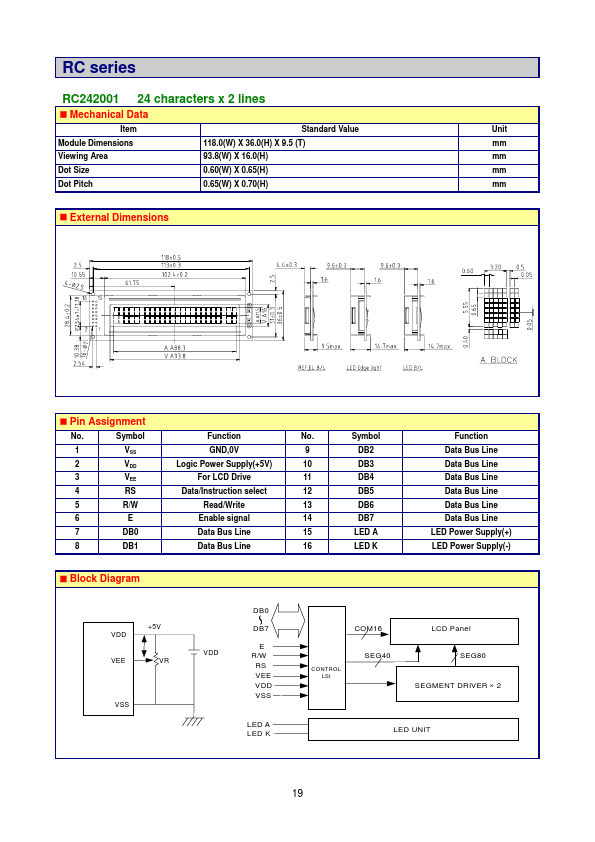
24-Characters x 2-Lines Display
| Part No. | RC242001 |
|---|---|
| Datasheet | RC242001 Download |
| Manufacturer | Apex Science |
| Description | 24-Characters x 2-Lines Display |
| Buy | Stock & Price |