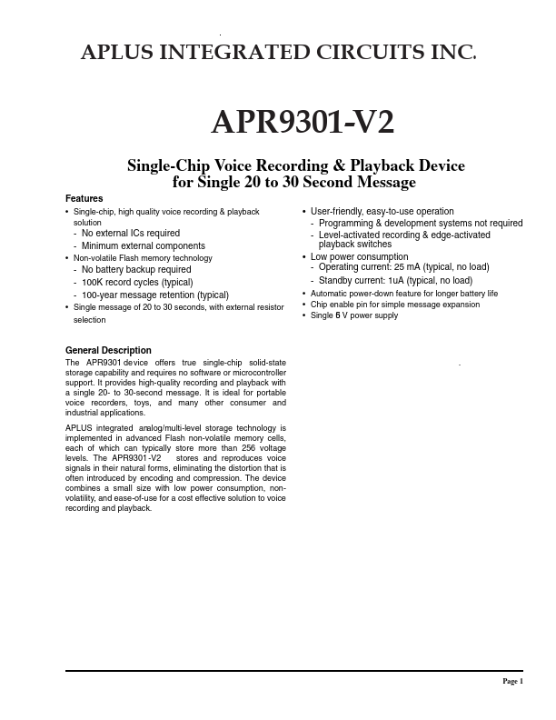
Apuls Intergrated Circuits APR9301-V2
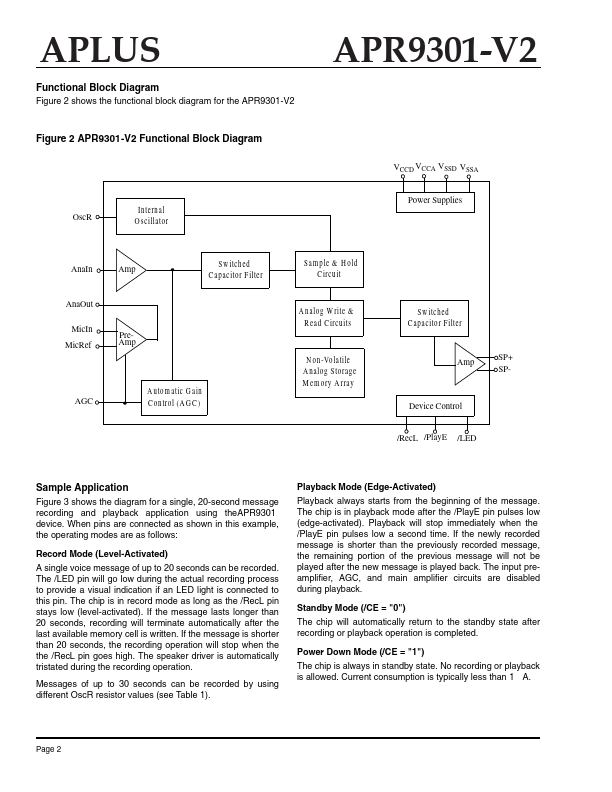
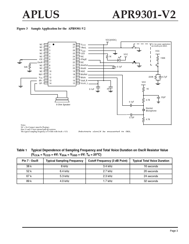
the APR9301-V2 APR9301-V2 VCCD VCCA VSSD VSSA Figure 2 APR9301 -V2 Functional Block Diagram Power Supplies OscR Internal O scillator AnaIn Amp S w itched C apacitor Filter S am ple & H old C ircuit AnaOut MicIn MicRef A nalog W rite & R ead C ircuits PreAmp S w itched C apacitor Filter N on-Volatile A nalog Storage M em ory A rray AGC Amp SP+ SP- A utom atic G ain C ontrol (A G C ) Device Control /RecL /PlayE /LED Sample Application Figure 3 shows the diagram for a single, 20-second message recording and playback application using theAPR9301 device. When pins are connected as shown in this example, the operating modes are as follows: Record Mode (Level-Activated) A single voice message of up to 20 seconds can be recorded. The /LED pin will go low during the actual recording process to provide a visual indication if an LED light is connected to this pin.| Part No. | APR9301-V2 |
|---|---|
| Datasheet | APR9301-V2 Download |
| Manufacturer |  Apuls Intergrated Circuits |
| Description | SINGLE-CHIP VOICE RECORDING & PLAYBACK DEVICE FOR SINGLE 20 TO 30 SECOND MESSAGE |
| Buy | Stock & Price |