Datasheet4U Logo Datasheet4U.com

ACPL-W314 - 0.6 Amp Output Current IGBT Gate Driver Optocoupler

This page provides the datasheet information for the ACPL-W314, a member of the ACPL-P314 0.6 Amp Output Current IGBT Gate Driver Optocoupler family.

Datasheet Summary

Description

The ACPL-P314/W314 consists of a GaAsP LED optically coupled to an integrated circuit with a power output stage.

These optocouplers are ideally suited for driving power IGBTs and MOSFETs used in motor control inverter applications.

Features

  • High speed response.
  • Ultra high CMR.
  • Bootstrappable supply current.
  • Available in Stretched SO-6 package.
  • Package Clearance/Creepage at 8mm (ACPL-W314).
  • Safety Approval: UL Recognized with 3750 Vrms for 1 minute per UL1577. CSA Approved. IEC/EN/DIN EN 60747-5-2 Approved with VIORM = 630VPEAK for option 060. Specifications.
  • 0.6 A maximum peak output current.
  • 0.4 A minimum peak output current.
  • 0.7 µs maximum prop.

📥 Download Datasheet

Datasheet preview – ACPL-W314

Datasheet Details

Part number ACPL-W314
Manufacturer Avago Technologies
File Size 487.93 KB
Description 0.6 Amp Output Current IGBT Gate Driver Optocoupler
Datasheet download datasheet ACPL-W314 Datasheet
Additional preview pages of the ACPL-W314 datasheet.
Other Datasheets by Avago Technologies

Full PDF Text Transcription

Click to expand full text
ACPL-P314 and ACPL-W314 0.6 Amp Output Current IGBT Gate Driver Optocoupler Data Sheet Description The ACPL-P314/W314 consists of a GaAsP LED optically coupled to an integrated circuit with a power output stage. These optocouplers are ideally suited for driving power IGBTs and MOSFETs used in motor control inverter applications. The high operating voltage range of the output stage provides the drive voltages required by gate controlled devices. The voltage and current supplied by this optocoupler makes it ideally suited for directly driving small or medium power IGBTs.
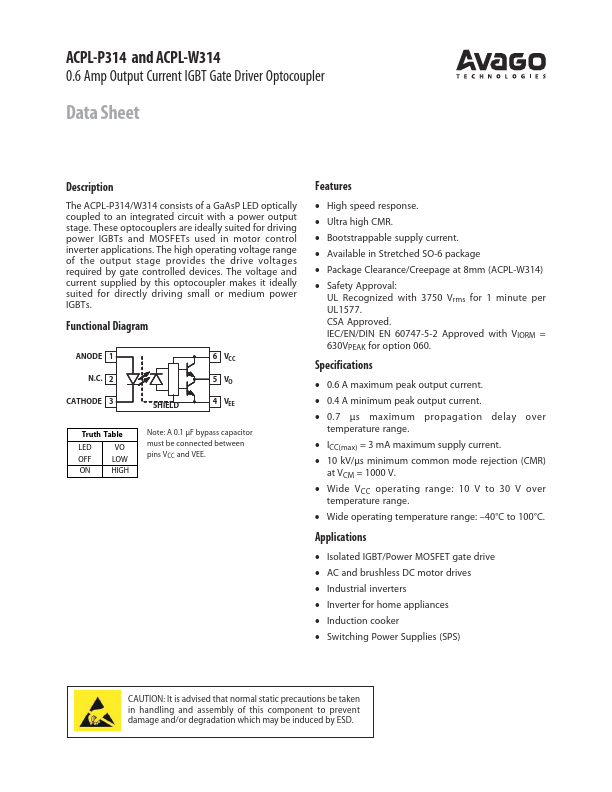
 Functional Diagram ANODE 1 N.C. 2 CATHODE 3 SHIELD 6 VCC 5 VO 4 VEE Truth Table LED VO OFF LOW ON HIGH Note: A 0.1 µF bypass capacitor must be connected between pins VCC and VEE. Features • High speed response.
Published: |