DESCRIPTION
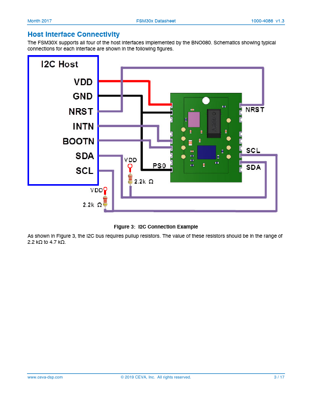
Supply voltage (2.4V to 3.6V) Ground Reserved. Do Not Connect Reserved. Do Not Connect Host interrupt Bootloader mode selection. Internal pullup. Protocol select 1. Internal pulldown. Ground Protocol select 0. SPI mode processor wake input. Internal pullup. Reserved. Do Not Connect Host Interface I2C data, SPI data output or UART transmit data Host Interface I2C clock, SPI clock or UART receive data Reserved. Do Not Connect Lower address bit of I2C device address. SPI data input. Internal pulldown. SPI chip select Reserved. Do Not Connect Reserved. Do Not Connect Reset. Internal pullup. Figure 2: FSM30X Pin Descriptions © 2019 CEVA, Inc. All rights reserved. 2 / 17 Month 2017 FSM30x Datasheet 1000-4086 v1.3 Host Interface Connectivity The FSM30X supports all four of the host interfaces implemented by the BNO080. Schematics showing typical connections for each interface are shown in the following figures. Figure 3: I2C Connection Example As shown in Figure 3, the I2C bus requires pullup resistors.