Calogic LLC 2N5484
N-Channel JFET
| Part No. | 2N5484 |
|---|---|
| Datasheet | 2N5484 Download |
| Manufacturer |  Calogic LLC |
| Description | N-Channel JFET |
| Buy | Stock & Price |
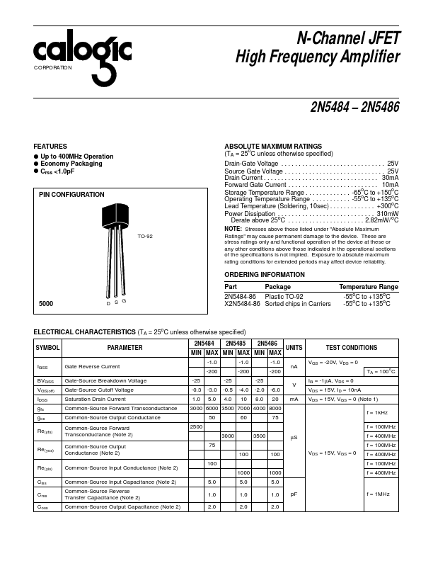
FEATURES
ABSOLUTE MAXIMUM RATINGS
(TA = 25oC unless otherwise specified) Drain-Gate Voltage . . . . . . . . . . . . . . . . . . . . . . . . . . . . . . 25V Source Gate Voltage . . . . . . . . . . . . . . . . . . . . . . . . . . . . . 25V Drain Current . . . . . . . . . . . . . . . . . . . . . . . . . . . . . . . . . 30mA Forward Gate Current . . . . . . . . . . . . . . . . . . . . . . . . . . 10mA Storage Temperature Range . . . . . . . . . . . . . -65oC to +150oC Operating Temperature Range . . . . . . . . . . . -55oC to +135oC Lead Temperature (Soldering, 10sec) . . . . . . . . . . . . . +300oC Power Dissipation . . . . . . . . . . . . . . . . . . . . . . . . . . . . 310mW Derate above 25oC . . . . . . . . . . . . . . . . . . . . . . 2.82mW/ oC TO-92● Up to 400MHz Operation
● Economy Packaging
● Crss <1.0pF PIN CONFIGURATION NOTE: Stresses above those listed under "
ABSOLUTE MAXIMUM RATINGS
" may cause permanent damage to the device. These are stress ratings only and functional operation of the device at these or any other conditions above those indicated in the operational sections of the specifications is not implied.