APPLICATIONS
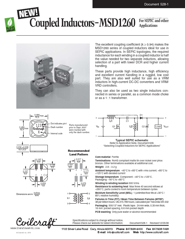
The excellent coupling coefficient (k ≥ 0.94) makes In SEPIC topologies, the required inductance for each winding in a coupled inductor is half the value needed for two separate inductors, allowing selection of a part with lower DCR and higher current handling. They can also be used as two single inductors connected in series or parallel, as a common mode choke or as a 1 : 1 transformer. 0.484 max 12,3 D1 + L1 C1 Dot indicates pin1 Dash number Internal code Parts manufactured prior to Sept. 2007 were marked with only the dash number. + + VOUT 0.484 max 12,3 123 X VIN Q1 L2 C2 Load – – Typical SEPIC schematic 0.236 ±0.008 6,0 ±0,2 Refer to Application Note, Document 639, “Selecting Coupled Inductors for SEPIC APPLICATIONS
” Recommended Land Pattern 0.197 5,0 0.138 3,5 0.157 4,0 2 3 1 4 0.217 5,5 0.197 5,0 3 2 4 1 0.177 4,5 0.059 1,5 0.079 2,0 Dimensions are in inches mm 1 L1 3 2 L2 4 Core material Ferrite Terminations RoHS compliant matte tin over nickel over phos bronze. Other terminations available at additional cost. Coilcraft lnc