SF20C04CF-G
SF20C04CF-G is Glass Passivated Super Fast Recovery Rectifier manufactured by Comchip Technology.
- Part of the SF20C01CF-G comparator family.
- Part of the SF20C01CF-G comparator family.
Features
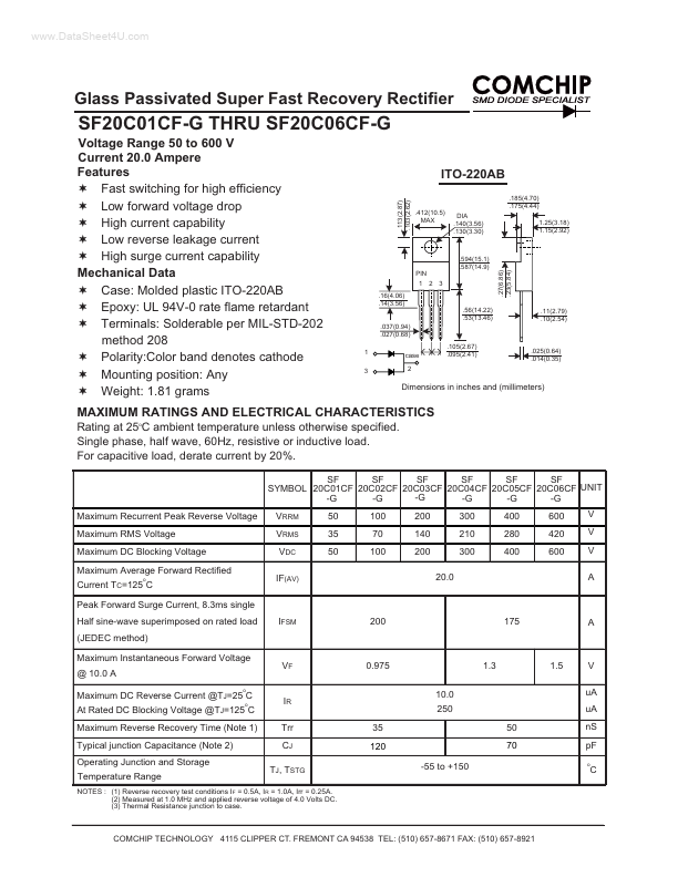
Fast switching for high efficiency Low forward voltage drop High current capability Low reverse leakage current High surge current capability Mechanical Data Case: Molded plastic ITO-220AB Epoxy: UL 94V-0 rate flame retardant Terminals: Solderable per MIL-STD-202 method 208 Polarity:Color band denotes cathode Mounting position: Any Weight: 1.81 grams ITO-220AB
.113(2.87) .103(2.62) .185(4.70) .175(4.44) .412(10.5) MAX DIA .140(3.56) .130(3.30) 1.25(3.18) 1.15(2.92)
.594(15.1) .587(14.9) PIN 1 2 3 .16(4.06) .14(3.56) .56(14.22) .53(13.46) .037(0.94) .027(0.68) 1 3 case 2 .105(2.67) .095(2.41) .025(0.64) .014(0.35) .27(6.86) .23(5.84)
.11(2.79) .10(2.54)
Dimensions in inches and (millimeters)
MAXIMUM RATINGS AND ELECTRICAL CHARACTERISTICS
Rating at 25o C ambient temperature unless otherwise specified. Single phase, half wave, 60Hz, resistive or inductive load. For capacitive load, derate current by 20%.
SF SF SF SF SF SF SYMBOL 20C01CF 20C02CF 20C03CF 20C04CF 20C05CF 20C06CF UNIT -G -G -G -G -G -G Maximum Recurrent Peak Reverse Voltage Maximum RMS Voltage Maximum DC Blocking Voltage Maximum Average Forward Rectified Current TC=125 C Peak Forward Surge Current, 8.3ms single Half sine-wave superimposed on rated load (JEDEC method) Maximum Instantaneous Forward Voltage @ 10.0 A Maximum DC Reverse Current @TJ=25 C At Rated DC Blocking Voltage @TJ=125 C Maximum Reverse Recovery Time (Note 1) Typical junction Capacitance (Note 2)
Operating Junction and Storage Temperature Range o o o
VRRM VRMS VDC IF(AV)
50 35 50
100 70 100
200 140 200 20.0
300 210 300
400 280 400
600 420 600
IFSM
0.975 10.0 250 35 120
-55 to +150
V u A u A
IR Trr CJ
TJ, TSTG
50 70 n S p F o
NOTES : (1) Reverse recovery test conditions IF = 0.5A, IR = 1.0A, Irr = 0.25A. (2) Measured at 1.0 MHz and applied reverse voltage of 4.0 Volts DC. (3) Thermal Resistance junction to case.
CHIP TECHNOLOGY 4115 CLIPPER CT. FREMONT CA 94538 TEL: (510)...