SR16C40C-G
SR16C40C-G is Schottky Barrier Rectifiers manufactured by Comchip Technology.
- Part of the SR16C20C-G comparator family.
- Part of the SR16C20C-G comparator family.
Features
:
Low forward voltage drop High current capability High reliability High surge current capability
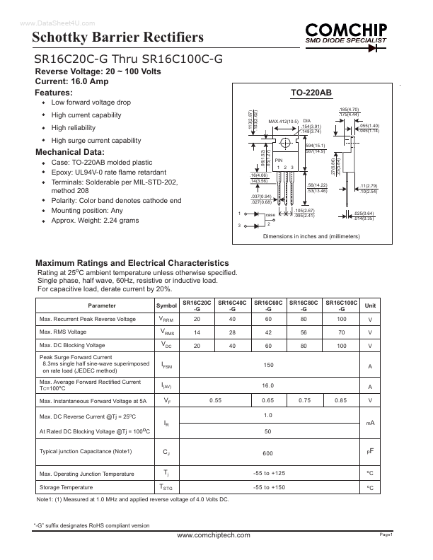
.06(1.52) .05(1.27) .113(2.87) .103(2.62) .185(4.70) .175(4.44) MAX.412(10.5) DIA .154(3.91) .148(3.74) .594(15.1) .587(14.9) PIN 1 2 3 .27(6.86) .23(5.84) .055(1.40) .045(1.14)
TO-220AB
Mechanical Data:
Case: TO-220AB molded plastic Epoxy: UL94V-0 rate flame retardant Terminals: Solderable per MIL-STD-202, method 208 Polarity: Color band denotes cathode end Mounting position: Any Approx. Weight: 2.24 grams
.16(4.06) .14(3.56) .56(14.22) .53(13.46) .037(0.94) .027(0.68) 1 3 case 2 .105(2.67) .095(2.41)
.11(2.79) .10(2.54)
.025(0.64) .014(0.35)
Dimensions in inches and (millimeters)
Maximum Ratings and Electrical Characteristics
Rating at 25o C ambient temperature unless otherwise specified. Single phase, half wave, 60Hz, resistive or inductive load. For capacitive load, derate current by 20%.
Parameter Max. Recurrent Peak Reverse Voltage Max. RMS Voltage Max. DC Blocking Voltage Peak Surge Forward Current 8.3ms single half sine-wave superimposed on rate load (JEDEC method) Max. Average Forward Rectified Current TC=100o C Max. Instantaneous Forward Voltage at 5A Max. DC Reverse Current @Tj = 25o C Symbol V RRM SR16C20C -G 20 14 20 SR16C40C -G 40 28 40 SR16C60C -G 60 42 60 150 SR16C80C -G 80 56 80 SR16C100C -G 100 70 100 Unit V V V
VRMS VDC IFSM I(AV) VF IR
16.0 0.55 0.65 1.0 0.75 0.85
A V m A
At Rated DC Blocking Voltage @Tj = 100o C
50 p F
Typical junction Capacitance (Note1)
CJ Tj TSTG
Max. Operating Junction Temperature Storage Temperature
-55 to +125 -55 to +150 o
C o C
Note1: (1) Measured at 1.0 MHz and applied reverse voltage of 4.0 Volts DC.
“-G” suffix designates Ro HS pliant version
.chiptech.
Page1
Schottky Barrier Rectifiers
RATINGS AND CHARACTERISTIC CURVES SR16C20C-G THRU SR16C100C-G
FIG.1
- FORWARD CURRENT DERATING CURVE
FIG.2
- MAXIMUM NON-REPETITIVE PEAK FORWARD SURGE CURRENT PEAK FORWARD SURGE CURRENT, AMPERES
Pulse...