MSTM-S3
MSTM-S3 is STRATUM 3 SIMPLIFIED CONTROL TIMING MODULES manufactured by Connor-Winfield.
- Part of the MSTM-S3_Connor comparator family.
- Part of the MSTM-S3_Connor comparator family.
DESCRIPTION
The Connor-Winfield Stratum 3 Simplified Control Timing Module acts as a plete system clock module for general Stratum 3 timing applications. The MSTM is designed for external control functions. Full external control input allows for selection and monitoring of any of four possible operating states: 1) Holdover, 2) External Reference #1, 3) External Reference #2, and 4) Free Run. The table below illustrates the control signal inputs and corresponding operational states: In the absence of External Control Inputs (A,B), the MSTM enters the Free Run mode and signals an External Alarm. The MSTM will enter other operating modes upon application of a proper control signal. Mode 1 operation (A=1, B=0) results in an output signal that is phase locked to the External Reference Input #1. Mode 2 operation (A=0, B=1) results in an output signal that is phase locked to External Reference Input #2. Holdover mode operation (A=1, B=1) results in an output signal at or near the frequency as determined by the latest (last) locked-signal input values and the holdover performance of the MSTM. Alarm signals are generated at the Alarm Output during Holdover and Free Run operation. Alarm Signals are also generated by loss-of-lock, loss of Reference, and by a Tune-Limit indication from the PLL. A Tune-Limit alarm signal indicates that the VCXO tuning voltage is approaching within 10% the limits of its lock capability and that the External Reference Input may be erroneous. A high level indicates an alarm condition. Realtime indication of the operational mode is available at unique operating mode outputs on pins 1-4. Control loop filters effectively attenuate any reference jitter and smooth out phase transients.
CNTL A CNTL B 2:4
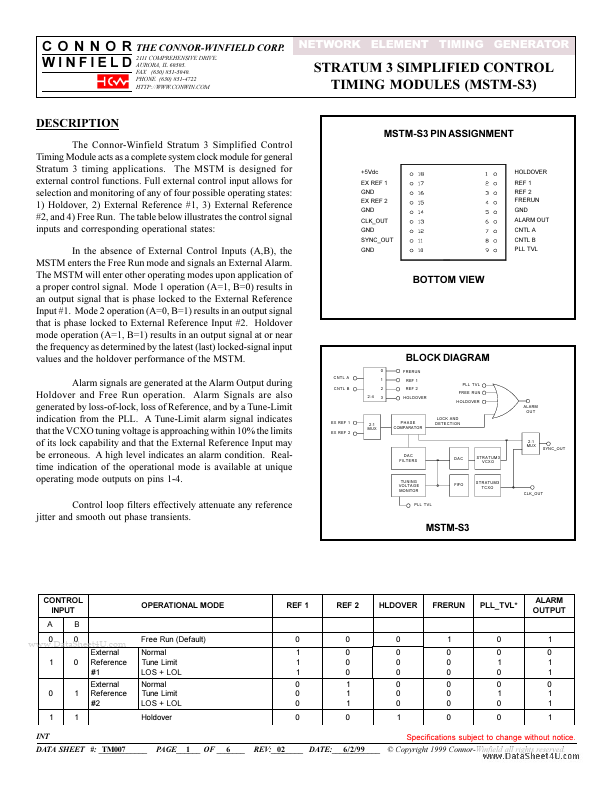
+5Vdc EX REF 1 GND EX REF 2 GND CLK_OUT GND SYNC_OUT GND
HOLDOVER REF 1 REF 2 FRERUN GND ALARM OUT CNTL A CNTL B PLL TVL
BOTTOM VIEW
BLOCK DIAGRAM
0 1 2 3 FRERUN REF 1 REF 2 HOLDOVER PLL TVL FREE RUN HOLDOVER ALARM OUT
EX REF 1 EX REF 2
2:1...