Datasheet4U Logo Datasheet4U.com

KTLP3502H - 8PIN RANDOM-PHASE TRIAC DRIVER PHOTOCOUPLER

Download the KTLP3502H datasheet PDF. This datasheet also covers the KTLP3502 variant, as both devices belong to the same 8pin random-phase triac driver photocoupler family and are provided as variant models within a single manufacturer datasheet.

General Description

The KTLP3502 series consist of a GaAs infrared emitting diode optically coupled to an non-zero-crossing silicon bilateral TRIAC and a main output power TRIAC.

These devices isolate low voltage logic from 115 VAC lines to provide random phase control of high current TRIACs or thyristors.

Key Features

  • s 1. Pb free and RoHS compliant 2. 400V peak blocking voltage 3. On-State R. M. S Current 0.5A. 4. Simplifies logic control of 115 VAC power 5. Non zero voltage crossing 6. Isolation voltage between input and output (Viso:5300Vms) 7. MSL class 1 8. Agency Approvals:.
  • UL Approved (No. E169586): UL1577.
  • c-UL Approved (No. E169586).
  • VDE Approved (No. 40020973): DIN EN60747-5-5.
  • Applica.

📥 Download Datasheet

Note: The manufacturer provides a single datasheet file (KTLP3502_COSMOElectronicsCorporation.pdf) that lists specifications for multiple related part numbers.

Datasheet Details

Part number KTLP3502H
Manufacturer Cosmo
File Size 243.51 KB
Description 8PIN RANDOM-PHASE TRIAC DRIVER PHOTOCOUPLER
Datasheet download datasheet KTLP3502H Datasheet

Full PDF Text Transcription (Reference)

The following content is an automatically extracted verbatim text from the original manufacturer datasheet and is provided for reference purposes only.

View original datasheet text
cosmo KTLP3502 Series 8PIN RANDOM-PHASE TRIAC DRIVER PHOTOCOUPLER  Description The KTLP3502 series consist of a GaAs infrared emitting diode optically coupled to an non-zero-crossing silicon bilateral TRIAC and a main output power TRIAC. These devices isolate low voltage logic from 115 VAC lines to provide random phase control of high current TRIACs or thyristors. These devices feature greatly enhanced static dv/dt capability to ensure stable switching performance of inductive loads.  
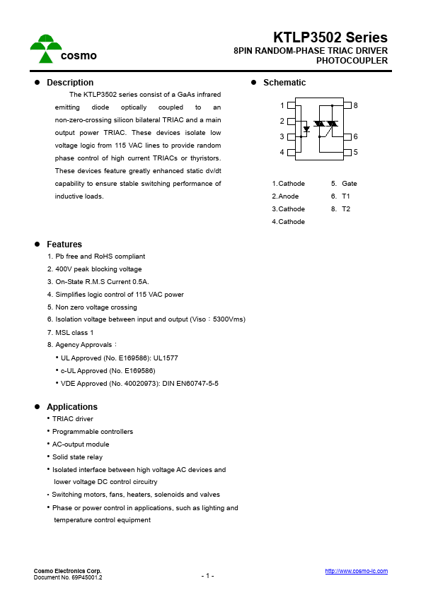
Schematic 1 2 3 4 8 6 5 1. Cathode 2. Anode 3. Cathode 4. Cathode 5. Gate 6. T1 8. T2  Features 1. Pb free and RoHS compliant 2. 400V peak blocking voltage 3. On-State R.M.S Current 0.5A. 4. Simplifies logic control of 115 VAC power 5. Non zero voltage crossing 6.