Datasheet4U.com
🌙
SK9172 Datasheet | DOLD
Part:
SK9172
Description:
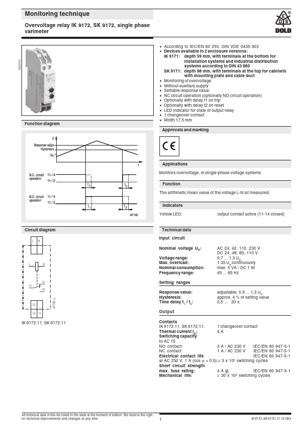
Overvoltage relay
Manufacturer:
DOLD
Size:
84.95 KB
SK9172 Datasheet (PDF) Download
Related SK9172 Datasheets
SK9171 Undervoltage relay
DOLD
SK9172
Key Features
According to IEC/EN 60 255, DIN VDE 0435-303
Devices available in 2 enclosure versions
×
Close