DS1212
FEATURES
Converts full CMOS RAM into nonvolatile memory Unconditionally write protects when VCC is out of tolerance Automatically switches to battery when power-fail occurs 4 to 16 decoder provides control for up to 16 CMOS RAMs Consumes less than 100 n A of battery current Tests battery condition on power-up Provides for redundant batteries Power fail signal can be used to interrupt processor on power failure Optional 5% or 10% power-fail detection Optional 28-pin PLCC surface mount package Optional industrial temperature range of -40°C to +85°C
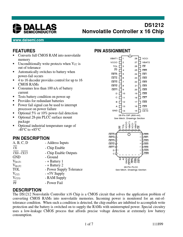
PIN ASSIGNMENT
VBAT1 VCCO TOL PF CE15 CE14 CE13 CE12 CE11 D C B A GND 1 2 3 4 5 6 7 8 9 10 11 12 13 14 28 27 26 25 24 23 22 21 20 19 18 17 16 15 VCCI VBAT2 CE CE0 CE1 CE2 CE3 CE4 CE5 CE6 CE7 CE8 CE9 CE10
28-Pin DIP (600-mil) See Mech. Drawings Section PF TOL VCCO VBAT1 VCCI VBAT2 CE
4 3 2 1 28 27 26 25 24 23 22 21 20 19 12 13 14 15 16 17 18
PIN DESCRIPTION
A, B, C, D
CE CE0
- CE15
GND VBAT1 VBAT2 TOL VCCI VCCO
- Address Inputs
- Chip...