BR101
BR101 is TECHNICAL SPECIFICATIONS OF SINGLE-PHASE SILICON BRIDGE RECTIFIER manufactured by Dc Components.
FEATURES
- Surge overload rating: 200 Amperes peak
- Low forward voltage drop
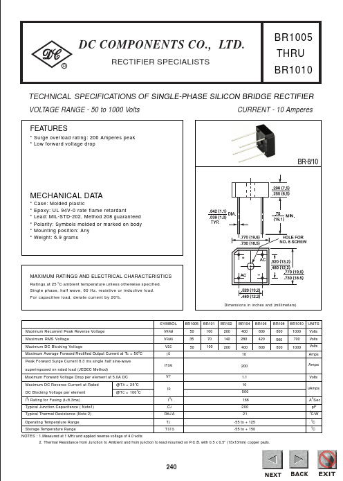
BR-8/10
MECHANICAL DATA
- -
- -
- - Case: Molded plastic Epoxy: UL 94V-0 rate flame retardant Lead: MIL-STD-202, Method 208 guaranteed Polarity: Symbols molded or marked on body Mounting position: Any Weight: 6.9 grams
MAXIMUM RATINGS AND ELECTRICAL CHARACTERISTICS
Ratings at 25 o C ambient temperature unless otherwise specified. Single phase, half wave, 60 Hz, resistive or inductive load. For capacitive load, derate current by 20%. Dimensions in inches and (millimeters)
SYMBOL Maximum Recurrent Peak Reverse Voltage Maximum RMS Voltage Maximum DC Blocking Voltage Maximum Average Forward Rectified Output Current at Tc = 50 C Peak Forward Surge Current 8.3 ms single half sine-wave superimposed on rated load (JEDEC Method) Maximum Forward Voltage Drop per element at 5.0A DC Maximum DC Reverse Current at Rated DC Blocking Voltage per element I 2t Rating for Fusing (t<8.3ms) Typical Junction Capacitance ( Note1) Typical Thermal Resistance (Note 2) Operating Temperature Range Storage Temperature Range NOTES : 1.Measured at 1 MHZ and applied reverse voltage of 4.0 volts @T A = 25 o C @T C = 100 o C IR I2t CJ RθJ A TJ T STG VF o
BR1005 50 35 50
BR101 100 70 100
BR102 200 140 200
BR104 400 280 400 10 200 1.1 10 500 166 200 21 -55 to + 125
BR106 600 420 600
BR108 800 560 800
BR1010 1000 700 1000
UNITS Volts Volts Volts Amps Amps Volts u Amps A 2 Sec p F
VRRM VRMS VDC IO IFSM
C/W
-55 to + 150
2. Thermal Resistance from Junction to Ambient and from junction to lead mounted on P.C.B. with 0.5 x 0.5" (13x13mm) copper pads.
NEXT NEXT NEXT
EXIT BACK BACK EX BACK EXIT
RATING AND CHARACTERISTIC CURVES (BR1005 THRU BR1010)
He Si atnk u Mo
Bo nti ar ng d
M ou nt in g
DC PONENTS CO., LTD.
NEXT NEXT NEXT
EXIT BACK BACK EX BACK...