M13
M13 is TECHNICAL SPECIFICATIONS OF SURFACE MOUNT SILICON RECTIFIER manufactured by Dc Components.
FEATURES
- ldeal for surface mounted applications
- Low leakage current
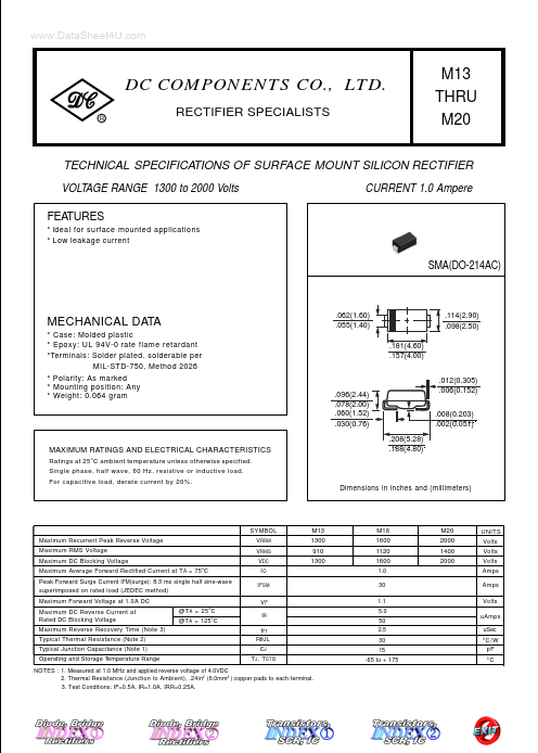
SMA(DO-214AC)
MECHANICAL DATA
- Case: Molded plastic
- Epoxy: UL 94V-0 rate flame retardant
- Terminals: Solder plated, solderable per MIL-STD-750, Method 2026
- Polarity: As marked
- Mounting position: Any
- Weight: 0.064 gram
.062(1.60) .055(1.40) .181(4.60) .157(4.00)
.114(2.90) .098(2.50)
.096(2.44) .078(2.00) .060(1.52) .030(0.76) .208(5.28) .188(4.80)
.012(0.305) .006(0.152) .008(0.203) .002(0.051)
MAXIMUM RATINGS AND ELECTRICAL CHARACTERISTICS
Ratings at 25 o C ambient temperature unless otherwise specified. Single phase, half wave, 60 Hz, resistive or inductive load. For capacitive load, derate current by 20%.
Dimensions in inches and (millimeters)
SYMBOL Maximum Recurrent Peak Reverse Voltage Maximum RMS Voltage Maximum DC Blocking Voltage Maximum Average Forward Rectified Current at T A = 75o C Peak Forward Surge Current I FM(surge): 8.3 ms single half sine-wave superimposed on rated load (JEDEC method) Maximum Forward Voltage at 1.0A DC Maximum DC Reverse Current at Rated DC Blocking Voltage Maximum Reverse Recovery Time (Note 3) Typical Thermal Resistance (Note 2) Typical Junction Capacitance (Note 1) Operating and Storage Temperature Range @T A = 25 o C @T A = 125 o C VRRM VRMS VDC IO I FSM VF IR trr RθJL CJ T J , T STG
M13 1300 910 1300
M16 1600 1120 1600 1.0 30 1.1 5.0 50 2.5 30 15 -65 to + 175
M20 2000 1400 2000
UNITS Volts Volts Volts Amps Amps Volts u Amps u Sec
C/ W p F
NOTES : 1. Measured at 1.0 MHz and applied reverse voltage of 4.0VDC 2. Thermal Resistance (Junction to Ambient), .24in2 (6.0mm 2 ) copper pads to each terminal. 3. Test Conditions: IF=0.5A, IR=1.0A, IRR=0.25A.
RATING AND CHARACTERISTIC CURVES (M13 thru M20)
DC PONENTS CO.,...