MBR356
MBR356 is SINGLE-PHASE SILICON BRIDGE RECTIFIER manufactured by Dc Components.
- Part of the MBR3505 comparator family.
- Part of the MBR3505 comparator family.
FEATURES
- Plastic case with heatsink for Maximum Heat Dissipation
- Diffused Junction
- High current capability
- Surge overload ratings
- 400 Amperes
- Low forward voltage drop
- High Reliability
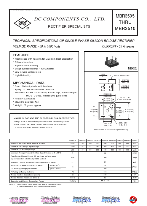
.500 (12.7) TYP. METAL HEAT SINK .310(7.9) .290(7.4) .480(12.2) .425(10.8) 1.142(29.0) 1.102(28.0) .673(17.1) .633(16.1)
MBR-25
MECHANICAL DATA
- Case: Molded plastic with heatsink
- Epoxy: UL 94V-0 rate flame retardant
- Terminals: Plated .25"(6.35mm) Faston lugs, Solderable per MIL-STD-202E, Method 208 guaranteed
- Polarity: As marked
- Mounting position: Any
- Weight: 25 grams approx.
.732(18.6) .692(17.6) AC
HOLE FOR NO. 8 SCREW
AC .673(17.1) 1.142(29.0) .633(16.1) 1.102(28.0)
MAXIMUM RATINGS AND ELECTRICAL CHARACTERISTICS
Ratings at 25 o C ambient temperature unless otherwise specified. Single phase, half wave, 60 Hz, resistive or inductive load. For capacitive load, derate current by 20%. Dimensions in inches and (millimeters) .582(14.8) .543(13.8) .033 x .250 (0.8 x 6.4)
SYMBOL Maximum Recurrent Peak Reverse Voltage Maximum RMS Bridge Input Voltage Maximum DC Blocking Voltage Maximum Average Forward Rectified Output Current at Tc = 55o C Peak Forward Surge Current 8.3 ms single half sine-wave superimposed on rated load (JEDEC Method) Maximum Forward Voltage Drop per element at 17.5A DC Maximum DC Reverse Current at Rated DC Blocking Voltage per element I t Rating for Fusing (t<8.3ms) Typical Junction Capacitance (Note1) Typical Thermal Resistance (Note 2) Operating and Storage Temperature Range NOTES : 1.Measured at 1 MHZ and applied reverse voltage of 4.0 volts. 2.Thermal Resistance from Junction to Case per leg.
MBR3505 MBR351 MBR352 MBR354 MBR356 MBR358 MBR3510 UNITS 50 35 50 100 70 100 200 140 200 400 280 400 35 400 1.1 10 500 664 300 2.2 -55 to +150
VRRM VRMS VDC IO I FSM VF IR I t CJ RθJ C T J, T STG
600 420 600
800 560 800
1000 700 1000
Volts Volts Volts Amps Amps Volts µAmps A 2 Sec p F C/W
@T A = 25 o C @T A = 100 o C
RATING AND...