S9004P2CT
S9004P2CT is 30A SCHOTTKY BARRIER RECTIFIER manufactured by Diodes Incorporated.
30A SCHOTTKY BARRIER RECTIFIER Features
- -
- -
- -
- Schottky Barrier Chip Guard Ring Die Construction for Transient Protection Low Power Loss, High Efficiency High Surge Capability High Current Capability and Low Forward Voltage Drop For Use in Low Voltage, High Frequency Inverters, Free Wheeling, and Polarity Protection Applications Plastic Material
- UL Flammability Classification 94V-0
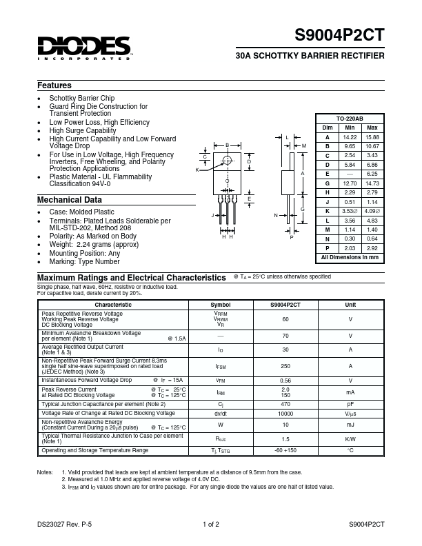
TO-220AB Dim
L B C K D A M
Min 14.22 9.65 2.54 5.84 ¾ 12.70 2.29 0.51 3.53Æ 3.56 1.14 0.30 2.03
Max 15.88 10.67 3.43 6.86 6.25 14.73 2.79 1.14 4.09Æ 4.83 1.40 0.64 2.92
A B C D E G H J
Mechanical Data
- -
- -
- - Case: Molded Plastic Terminals: Plated Leads Solderable per MIL-STD-202, Method 208 Polarity: As Marked on Body Weight: 2.24 grams (approx) Mounting Position: Any Marking: Type Number
All Dimensions in mm @ TA = 25°C unless otherwise specified
Maximum Ratings and Electrical Characteristics
Single phase, half wave, 60Hz, resistive or inductive load. For capacitive load, derate current by 20%. Characteristic Peak Repetitive Reverse Voltage Working Peak Reverse Voltage DC Blocking Voltage Minimum Avalanche Breakdown Voltage per element (Note 1) @ 1.5A Average Rectified Output Current (Note 1 & 3) Non-Repetitive Peak Forward Surge Current 8.3ms single half sine-wave superimposed on rated load (JEDEC Method) (Note 3) Instantaneous Forward Voltage Drop Peak Reverse Current at Rated DC Blocking Voltage @ i F = 15A @ TC = 25°C @ TC = 125°C Symbol VRRM VRWM VR ¾ IO IFSM v FM IRM Cj dv/dt W Rq Jc Tj, TSTG
S9004P2CT 60 70 30 250 0.56 2.0 150 470 10000 10 1.5 -60 +150
Unit V V A A V m A p F V/ms m J K/W °C
Typical Junction Capacitance per element (Note 2) Voltage Rate of Change at Rated DC Blocking Voltage Non-repetitive Avalanche Energy (Constant Current During a 20ms pulse) @ TC = 125°C Typical Thermal Resistance Junction to Case per element (Note 1) Operating and Storage Temperature Range
Notes:
1. Valid provided that leads are kept...